
V70R AWD L5-2.3L Turbo VIN 52 B5234T6 (1998)
Exhaust Manifold: Description and Operation
Legend
-
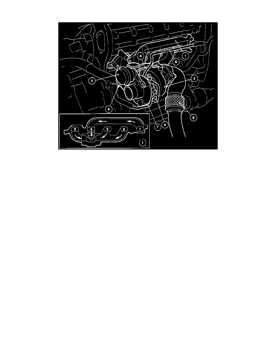
1 Exhaust manifold
-
2 Turbocharger (TC)
-
3 Pressure regulator
-
4 Link
-
5 Bypass valve
-
6 Oil inlet
-
7 Coolant inlet
-
8 Coolant return
-
9 Flexible joint (bellows type)
Exhaust Manifold And Turbo Charger (TC)
The illustration shows the exhaust manifold and TC, which are normally covered by two heat shields made of special double layer aluminium plate.
Exhaust manifold (1) is made in heat resistant cast iron and is small to save space. There are three separate passages from the exhaust passage to the
TC to prevent pulses in the exhaust gases from interfering with each other and to accelerate the TC turbine as quickly as possible. The exhaust
passages in the manifold for cylinders 4 and 1 are connected, as are the exhaust passages for cylinders 2 and 3, while cylinder 5 has its own passage.
This configuration is based on the engine firing order (1-2-4-5-3).
The TC (2) features:
-
A pressure regulator (3) which regulates the wastegate valve via a link (4). The pressure in the regulator is controlled by an electronically
controlled TC valve. If the TC valve stops working the pressure regulator ensures that boost pressure is limited to 135 kPa (19.5 psi) (absolute
pressure).
-
Bypass valve (5) which damps pressure surges in the intake manifold when the throttle is closed suddenly by routing some of the air from the TC
pressure side to its suction side.
-
Oil inlet (6) and return connector (hidden by the TC).
-
Coolant inlet (7) and return connector (8).
The exhaust system features a new type of flexible connection (9), which consists of a number of corrugated layers of metal enclosed in a metal based
braid. Very little heat is lost through the joint which helps to "trigger" the TWC quickly.