
V70R AWD L5-2.3L Turbo VIN 52 B5234T6 (1998)
If the camber angle is outside these values, see Adjusting camber angle.
Adjusting Camber Angle
Note! Adjust the camber angle if it lies outside the 0° ± 1° tolerance when checked. The variation between left and right sides must not exceed 1°.
Carry out the following when adjusting:
Raise cars and remove wheel
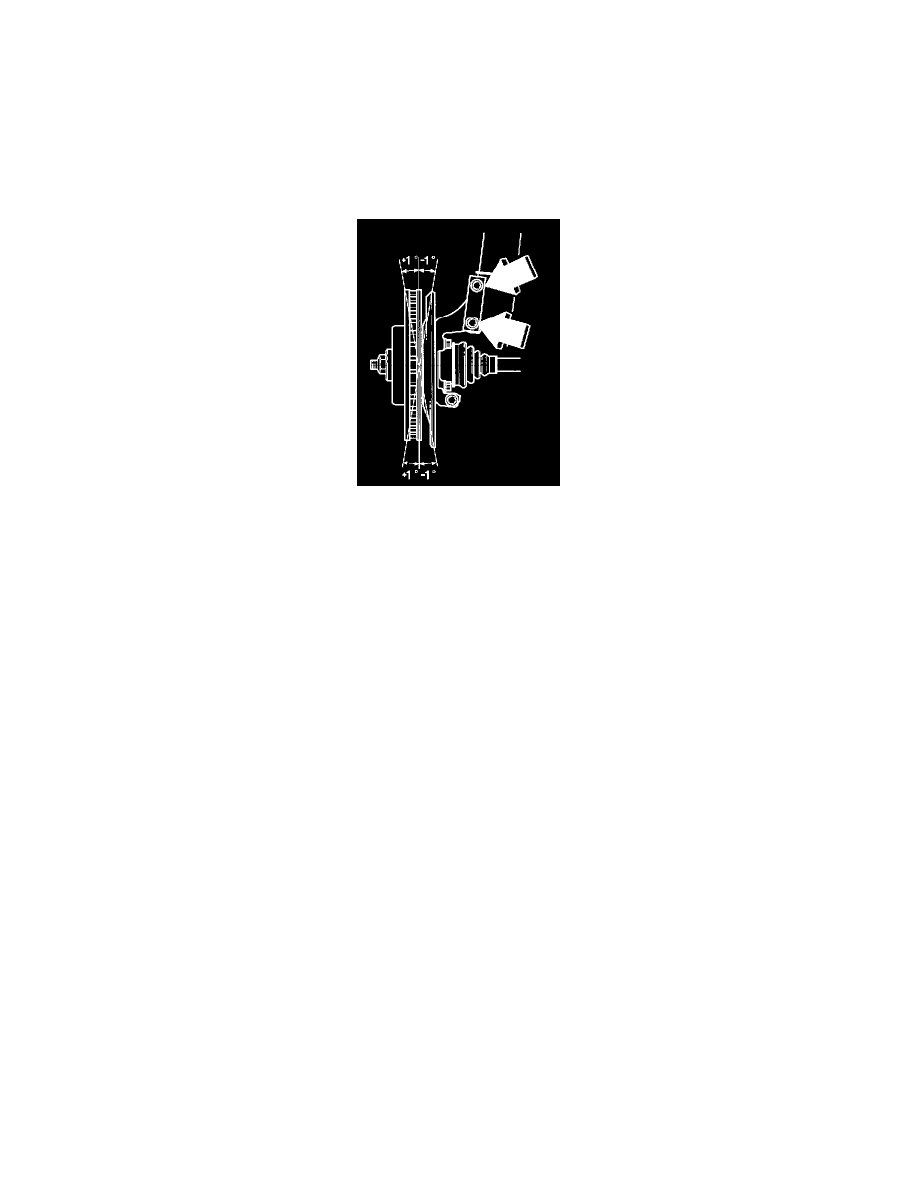
Cars with sleeves in the stub axles;
Remove the upper, if necessary both sleeves from the stub axle. This depends on how large the adjustment needs to be. A sleeve gives an angle change
of approximately 0.5°. For both sleeves the change is approximately 1°.
Cars without sleeves in the stub axles;
Replace screws and nuts and adjust as follows.
Note! Install new screws and nuts to stub axle
Tighten the screws slightly but not more than that necessary to allow the stub axle to be moved with some resistance, in or out in relation to the shock
absorber strut. Turn stub axle in or out as far as the play between the holes a screw allows.
Post adjustment, tighten both the screws to 65 Nm (47.9 ft. lbs.) a angle-tighten 90°.
Install Wheels
Lubricate hub guide for rims with suitable rustproofing agent.
Install wheel studs lightly. Tighten crosswise to 110 Nm (81.1 ft. lbs.)
Check camber angle and toe-in again.
Checking Caster Angle
Check the caster angle on both sides. Correct value: 3.35° ± 1.0°. The caster angle must not vary by more than 1.0 ° between the left and right sides.
Checking Toe-In
Check that the instruments are adjusted in relation to each other on front and rear axles. This is important so that the front wheel toe-in be adjusted in
relation to the car's thrust line. Thrust line is the line created when the rear wheels toe-in angles are equally divided, see illustration.
Note! The difference between the wheel symmetry line and the thrust line is called the thrust angle. This angle may deviate by a maximum of 15°
from the symmetry line.
A. Wheel symmetry line
B. Thrust line
C. Thrust angle
Note! The differences in the adjacent diagram are exaggerated in order to illustrate the differences.