
V70R AWD L5-2.3L Turbo VIN 52 B5234T6 (1998)
-
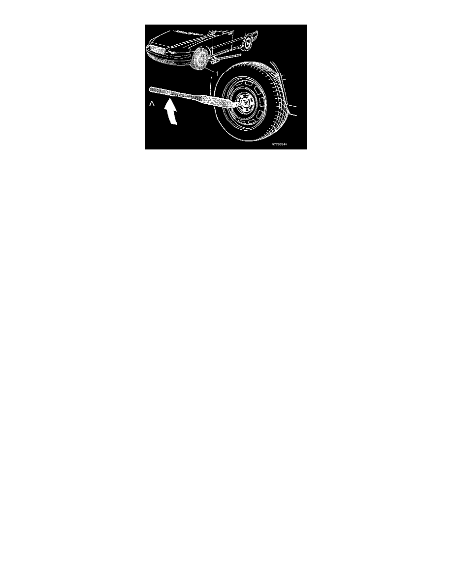
Position a torque wrench horizontally as illustrated. Read the torque value.
Note!
It is important that the torque wrench points towards the center of the wheel to provide the correct torque reading.
-
Turn the torque wrench half a turn (180°) clockwise with even torque for 25 seconds.
-
The torque must be GREATER than 50 Nm (37 lb ft) during the entire turn.
The test method assumes that all the other components included in the system function correctly If the torque is below 50 Nm (37 lb ft), the viscous
coupling is outside the specification and/or damaged.
7
The function of the freewheel unit
A freewheel unit is connected to the viscous coupling. It is located after the viscous coupling and has two functions:
-
Dis-engaging rear-wheel drive during braking.
-
Engaging four-wheel drive when reversing.
The freewheel unit has an input and an output shaft. These shafts can be connected via a freewheel and via a centrifugal roller lock-up mechanism.
The freewheel unit, which has a centrifugal roller lock-up mechanism, also makes it possible to reverse with four-wheel drive at up to approximately 50
km/h (30 mph).
Freewheel
-
When driving forward, power can be transmitted from the input shaft to the output shaft (rear axle) via the freewheel.
-
During braking the rear wheels may rotate faster than the front wheels. In this case the freewheel is driven in the (opposite) direction by the output
shaft. No power can be transmitted this way because the freewheel is free. The rear wheels can never drive the front wheels thereby negatively affect
braking stability.
-
When reversing, the freewheel is driven by the input shaft in the "opposite" direction. The freewheel is free and cannot transmit power. In certain
cases, power can instead be transmitted via the centrifugal lock-up mechanism.
Centrifugal lock-up mechanism
The centrifugal lock-up mechanism consists of:
-
Centrifugal weights in the form of ball bearings.
-
A spring-loaded cage with a ball holder. The ball holder has ramps and six small ball bearings.
-
Internal cutouts in the input shaft.