
V70R AWD L5-2.3L Turbo VIN 52 B5234T6 (1998)
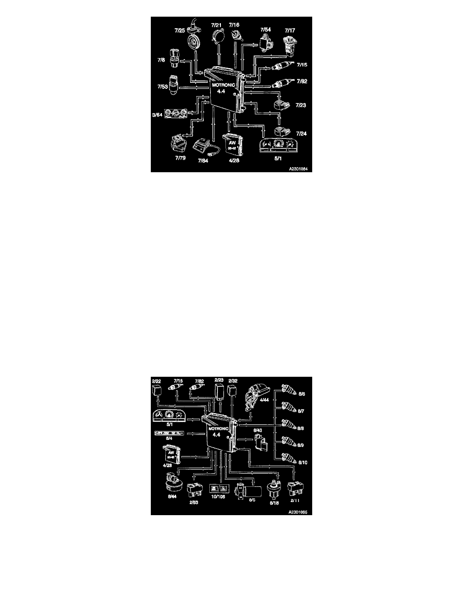
The Engine Control Module receives signals describing running conditions from the following components:
^ Engine speed and crankshaft position, from the Engine Speed (RPM) Sensor at the flywheel (7/25)
^ Working cycle in cylinders, from the Camshaft Position (CMP) Sensor (7/21)
^ Engine load, from the Mass Air Flow (MAF) Sensor (7/17)
^ Engine temperature, from the Engine Coolant Temperature (ECT) Sensor (7/16)
^ Throttle angle, from the Throttle Position (TP) Sensor (7/54)
^ Oxygen content of the exhaust gases upstream of the catalytic converter, from the front Heated Oxygen Sensor (HO2S) (7/15)
^ Oxygen content of the exhaust gases downstream of the catalytic converter, from the rear Heated Oxygen Sensor (HO2S) (7/82)
^ Engine knock (if present), from the two Knock Sensors (KS) (7/23 and 7/24)
^ Vehicle speed, from the Combined Instrument Panel (5/1)
^ Imminent gear-shifting, from the Automatic Transmission Control Module (TCM) (4/28) (automatics only)
^ Gear selector lever in Park/Neutral or DRIVE position, from the Automatic Transmission Control Module (TCM) (4/28)
^ Request to light the Malfunction Indicator Lamp (MIL) from the Automatic Transmission Control Module (TCM) (4/28)
^ Vertical acceleration of the car from the Accelerometer (7/79) to determine if the car is being driven on an uneven road, misfire diagnostic
^ If A/C is selected, from the A/C system Control Panel (3/54) A/C compressor ON signal, from the Pressure Switch (Pressostat) (7/53)
^ Pressure in the A/C unit, from the A/C Pressure Sensor (7/8)
^ Pulsed Secondary Air Injection System (PAIR) Pump Valve (8/43)
^ Fuel tank pressure from the Fuel Tank Pressure Sensor (7/84).
CONTROL FUNCTIONS
The Engine Control Module controls the following components and functions on the basis of these input signals:
^ Main relay (2/32)
^ Fuel pump, by activating the Fuel Pump Relay (2/23)
^ Fuel injection, by operating the Injectors (8/6-8/10) individually