
V70R AWD L5-2.3L Turbo VIN 52 B5234T6 (1998)
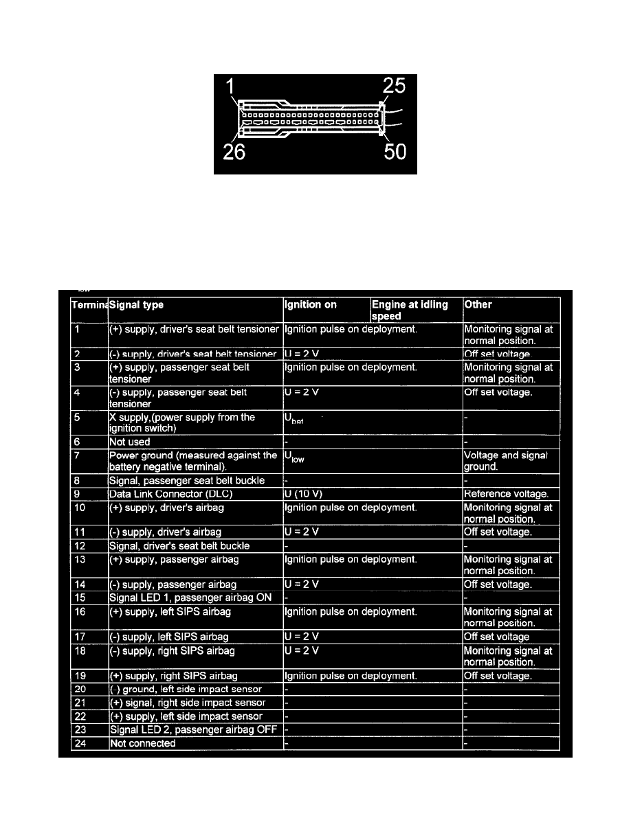
SRS Sensor Module: Connector Views
SRS Signal Specification
General
All values given below are between the respective terminal in column 1 and terminal 6 (power ground) unless otherwise stated in brackets after the
table entry.
U =
DC voltage in volts (V)
U low = Voltage approximately 0 V
U bat = Battery voltage (V)
Terminal 1 - 24