
V70R AWD L5-2.3L Turbo VIN 52 B5234T6 (1998)
-
Air duct to control module box.
-
Vacuum hose to Pulsed Secondary Air Injection System (PAIR) Solenoid Valve.
-
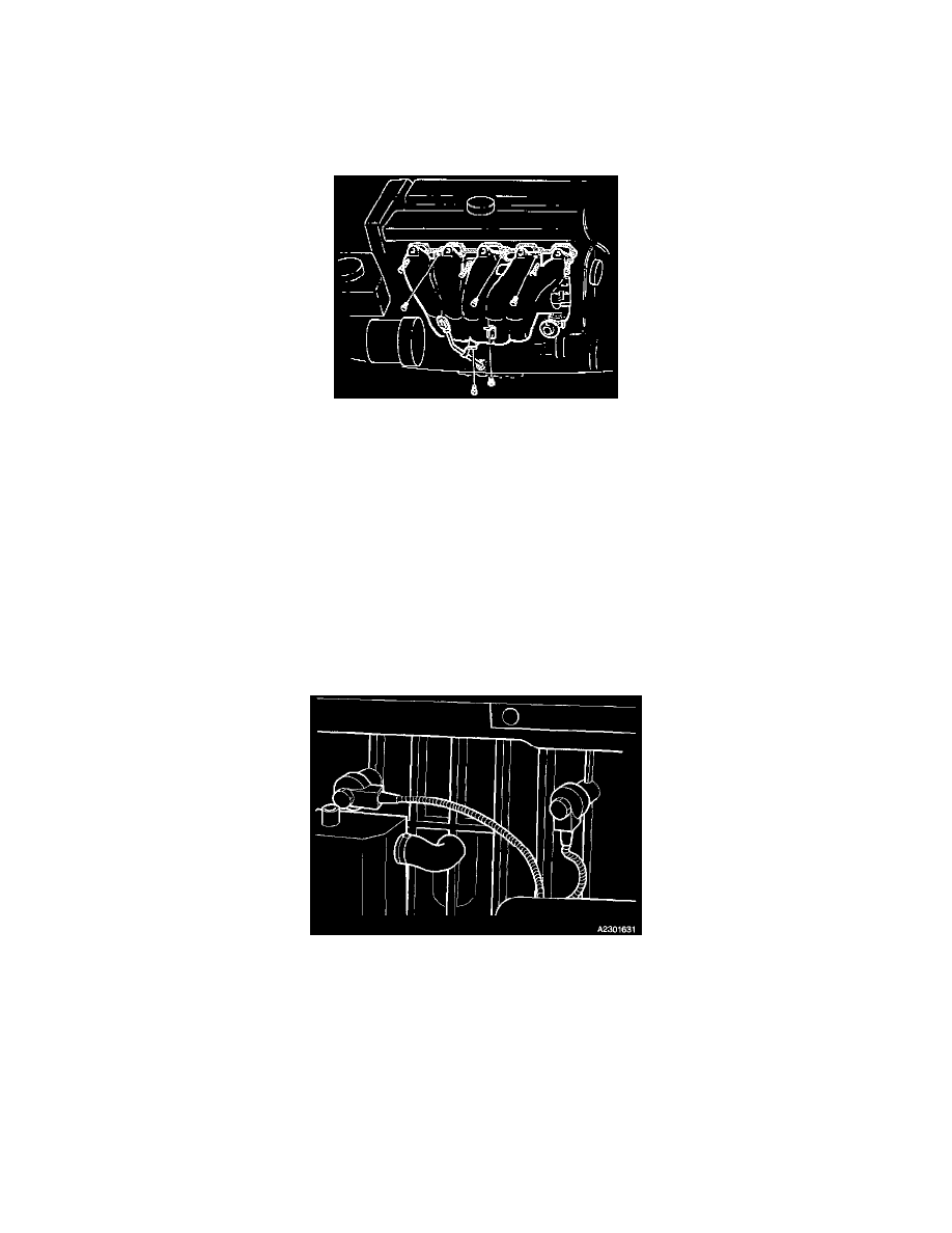
Hose to Turbocharger (TC) Control Valve from intake manifold.
-
Hose to crankcase ventilation from front edge of intake manifold.
-
Idle Air Control (IAC) Valve and Throttle Position (TP) Sensor connectors.
-
Brake system servo hose.
-
Injector cable harness clip.
Removing Intake Manifold
Remove:
-
Upper intake manifold screws (3).
-
Dipstick from intake manifold.
-
Lower intake manifold screws.
-
Intake manifold support bracket screw.
-
Intake manifold by lifting it approx. 20 mm, to release intake manifold from engine.
Removing Knock Sensors
Remove:
-
The large hose on the flame trap.
-
Knock Sensor (KS) connector.
-
Knock Sensors (KS).
Installing Knock Sensors
Install:
-
Knock sensors (KS) and tighten.
Tightening torques 20 Nm (14.76 ft.lb).
NOTE! Front knock sensor (KS) must be tightened in the 3 o'clock position and rear knock sensor (KS) in the half-past five position.
-
Knock sensor (KS) connector.
-
Flame trap hose.