
V70R AWD L5-2.3L Turbo VIN 52 B5234T6 (1998)
-
Tighten to: 25 Nm.
8. Remove the cables pins from socket.
-
Push in locking device beneath socket and push out red lock lug slightly.
9. Installation:
-
Lift up cables between oil cooler hose and control system cover.
-
Reinstall splashguard under engine.
-
Route the cables under gear position sensor.
-
Take care not to damage the cables.
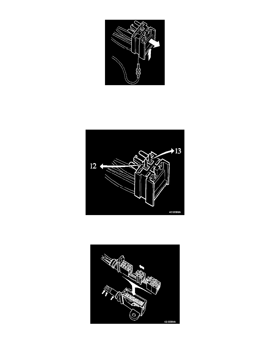
10. Reconnect cables to socket;
-
Pin 12: blue/red cable
-
Pin 13: blue/black cable
-
Check pins are correctly positioned in socket.
11. Reconnect connector halves.
-
Make sure rubber seal is in place.