
V70R AWD L5-2.3L Turbo VIN 60 B5244T2 (2000)
housing.
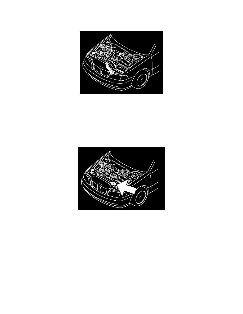
Connect the pressure and temperature sensor connectors on the charge air pipe leading to the throttle housing.
Install
-
the hoses (small) to the hose bracket on the engine block (front left)
-
the hoses (small) to the induction pipe in accordance with the marking
-
the hose (large) to the induction pipe
-
the two plastic washers/spacers to the fan shroud
-
the four screws holding the fan shroud in the upper edge
Connect the connector to the upper right corner of the fan shroud.
-
the pipe to the control module cover
-
the EVAP valve and its downward hose to the lower part of the fan shroud Connect the connector to the EVAP valve and the connectors on the fan
shroud (nearest the battery and fan).
-
wire clamp
-
the two smaller contacts to He relay
-
cooling fall relay
-
inlet pipe between front plate and air filter.