
V70R AWD L5-2.3L Turbo VIN 62 B5234T8 (1999)
Explanation Of Symbols Fig. 2
Table
Table
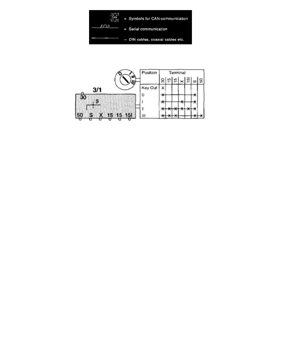
Certain multi-point switches are described using a Table. The table is used to read off when the terminals are electrically connected to each other.
Example. In position III, terminal 30 is connected to terminals 15A, S, and 50.
List of Components By Component Number
1/1
Battery
2/1
Main lighting relay with bulb failure warning sensor
2/2
Fog light relay
2/4
Windshield wiper intermittent relay
2/5
Seat belt reminder/ key warning relay
2/6
Overload relay 15I-supply
2/11
Engine cooling fan relay
2/14
Glow plug relay
2/16
Tailgate wiper intermittent relay
2/22
A/C relay
2/23
Fuel pump relay
2/30
Overload relay X-supply
2/32
Main relay, fuel system
2/35
Starter motor relay
2/43
Heated rear seat relay
2/44
Relay, heated rear window door mirrors
2/54
Relay 30-supply cargo compartment
2/67
Trunk lid opening relay
2/74
Relay heating plugs coolant
2/76
Control module central locking/ alarm
2/77
Relay alarm horn
2/99
Relay left-hand side window lift mechanism
2/100
Relay right-hand side window lift mechanism
2/134
Electronic throttle module (ETM) relay
3/1
Ignition switch
3/2
Light switch
3/3
Turn signal/high and low beam switch
3/4
Electrical switch module, cruise control
3/6
Hazard warning signal flasher switch