
V90 L6-2.9L VIN 96 B6304S (1998)
Control Module: Description and Operation
GENERAL
The transmission control system has four unique connectors, one for Transmission Control Module (TCM) (A) and three on the transmission itself (B.
C, and D). Apart from that the transmission control system wiring is incorporated with the other cable harnesses in the car (mainly on its lefthand
side).
SIGNAL VOLTAGE LEVEL
The system works at 12 V signal voltage on those terminals in the TCM connected to the engine control module (ECM). Refer to Signal Description,
as described under Test Box and Parameter Tables. See: Testing and Inspection/Initial Inspection and Diagnostic Overview Testing and Inspection,
Transmission Control Systems.
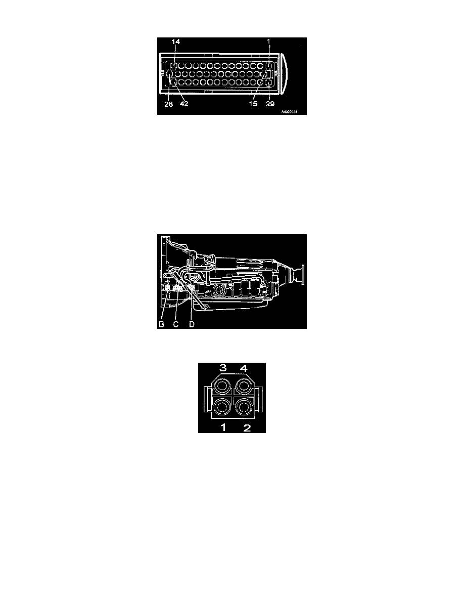
TCM CONNECTOR (A)
The illustration shows the terminals on the wiring connector that is connected to the TCM.
TRANSMISSION CONNECTORS (B. C, AND D)
There are three connectors (B. C and D) on the front left of the transmission to connect it with the control system.
Part 1 of 2