
XC60 FWD L6-3.2L VIN 96 B6324S2 (2010)
information. The level on the bus wire is normally high (approx 13 V) via a pull-up resistance, but is taken down to a low level (approx 1 V) when one of
the nodes on the bus transmits.
The LIN protocol is a supplement to CAN. LIN is a less expensive alternative to CAN and is used where the transfer rate and performance is not as
critical.
Besides a reduction in the number of wires, LIN is adapted for more basic communications circuits, which means the internal clock circuit in a slave
node can be an inexpensive oscillating circuit (a.k.a. RC circuits) instead of crystals or ceramic oscillators that are used in systems with greater
sensitivity to time differences.
This means that control module costs for the LIN standard can be kept down.
A synchronization procedure is used in each message on LIN in order to make communications, which are still time-dependent, possible. A number of
bits at the start of each message are used so that the clock circuit in each slave control module can adjust to the correct frequency so that the subsequent
data in the message can be received error-free.
If the LIN bus is inactive for a specific period of time, the slave nodes switch to sleep mode to reduce power consumption.
The transfer rate on LIN can lie between 5 and 20 kbit/s, but Volvo uses 9.6 kbit/s. This can be compared to the transfer rate on the CAN network which
is 125-500 kbit/s.
1 kbit/s = 1000 bits per second.
The reason why Volvo has selected a transfer rate of 9.6 kbit/s is the balance between performance and transfer quality. A higher transfer rate can be
used in some applications.
On a LIN bus there is always one control module that is the main control module (a.k.a. master node). All other control modules on the same LIN bus are
slave nodes.
The master node contains a list describing which slave nodes are connected on the LIN bus in question. The list in the master node also describes which
messages can be sent on the LIN bus and in which order.
Messages are sent in order according to the list in the master node with a specific time delay between messages, so that any responses from the slave
nodes can be received by the master node.
What the slave nodes shall do and/or which data is to be sent as a response when the slave node receives a message is in turn described in a list that is
programmed into each slave node. If a slave node has not managed to respond before it is time for the next message to be sent from the master node, the
master node will start to send nevertheless and the slave node will be interrupted during its transmission.
The maximum length of a bus wire is set to 35 m (114.83 ft). The high level on LIN means battery voltage, i.e. approx 9-18 V, yet all circuits connected
to the bus must withstand up to approximately 25 V.
The LIN bus is terminated to the battery voltage with a pull-up resistance on all nodes, the master mode with 1 kohms and the slave nodes with 20-47
kohms, usually 30 kohms.
This means that in sleep mode the voltage on the LIN bus is approximately 13 V and the dominant level on the bus (that is to say when a "1" is
transmitted and a node takes down the bus to a low level during the transmission) is approximately 1 V.
Hint: The voltage on the communication wire is dependent on the supply voltage. The guideline is that the average value during communication is
approximately 2/3 of the supply voltage. With a normal supply voltage and normal communication, the average voltage on the LIN bus lies at
approximately 7-8 V.
The residue voltage level depends on the internal protection diodes in the control module.
The slave nodes also have a diode in series with the pull-up resistance to prevent the connected components from loading the bus by leading current the
back-way if they do not have a power supply.
Wiring
The communication wire used on LIN is a single, unscreened conductor, which includes the most common cable harnesses in the vehicle. On account of
the wire being unscreened, some restrictions due to EMC reasons can apply to wire routing.
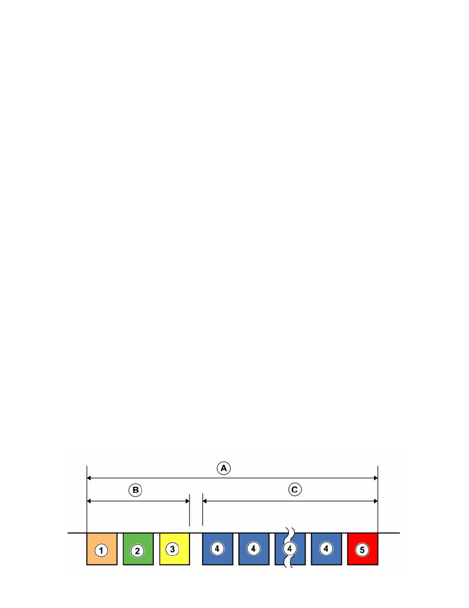
LIN message
Complete message