
XC70 L5-2.5L Turbo VIN 59 B5254T2 (2003)
Air Flow Meter/Sensor: Description and Operation
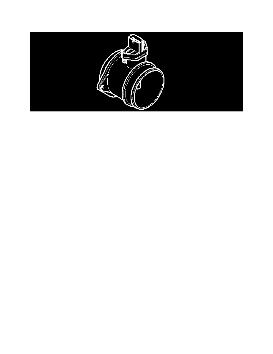
Mass Air Flow (MAF) Sensor (2002-2004)
The mass air flow (MAF) sensor gauges the air mass sucked into the engine. It continuously transmits signals to the engine control module (ECM) about
the mass of the intake air. This data is used by the engine control module (ECM) to calculate:
-
the injection period
-
the ignition timing
-
turbocharger (TC) boost pressure (turbocharged engines only)
-
the engine load.
The transmission control module (TCM) also uses this data for its gear shift calculations. This data is transmitted to the transmission control module
(TCM) from the engine control module (ECM) via the high speed side of the Controller area network (CAN).
The mass air flow (MAF) sensor consists of a plastic housing with connectors, test electronics and an aluminum heat sink. The test electronics in the
mass air flow (MAF) sensor consist of a hot film comprised of four resistors. The hot film is cooled by the air flow to the engine.
The mass air flow (MAF) sensor is supplied with battery voltage by the system relay and is grounded in the engine control module (ECM). The signal
from the sensor is analogue and varies between approximately 1-5 V depending on the air mass. Low air flow (low mass) results in low voltage, high air
flow (high mass) gives high voltage. No air flow gives a reading of approximately 1 V.
The mass air flow (MAF) sensor is positioned between the air cleaner (ACL) housing and the intake manifold.
The shape of the mass air flow (MAF) sensor is slightly different on naturally aspirated engines and also contains an air temperature sensor.
The engine control module (ECM) can diagnose the mass air flow (MAF) sensor. The signal can be read using VADIS/VIDA.
Air mass
The mass air flow (MAF) sensor transmits signals to the engine control module (ECM) about the mass of the intake air. This data is used by the engine
control module (ECM) to calculate:
-
the injection period
-
the ignition timing
-
turbocharger (TC) boost pressure (turbocharged engines only)
-
the engine load.
The transmission control module (TCM) also uses this data for its gear shift calculations. This data is transmitted to the transmission control module
(TCM) from the engine control module (ECM) via the high speed side of the Controller area network (CAN).
The mass air flow (MAF) sensor consists of a plastic housing with connectors, test electronics and an aluminum heat sink. The test electronics in the
mass air flow (MAF) sensor consist of a hot film comprised of four resistors. The hot film is cooled by the air flow to the engine.
The mass air flow (MAF) sensor is supplied with battery voltage by the system relay and is grounded in the engine control module (ECM). The signal
from the sensor is analogue and varies between approximately 1-5 V depending on the air mass. Low air flow (low mass) results in low voltage, high air
flow (high mass) gives high voltage. No air flow gives a reading of approximately 1 V.
Intake temperature
The temperature sensor detects the temperature of the intake air after the charge air cooler (CAC). This data is used by the engine control module (ECM)
to calculate the boost pressure control (turbocharger (TC) and to calculate the injection period. The control module also controls certain diagnostic