XC70 L5-2.5L Turbo VIN 59 B5254T2 (2003)

Checking for a short-circuit in the CAN bus system, low speed network
Checking for a short-circuit
Disconnect the upper electronic module from the bus cable (disconnect the connector from the control module).
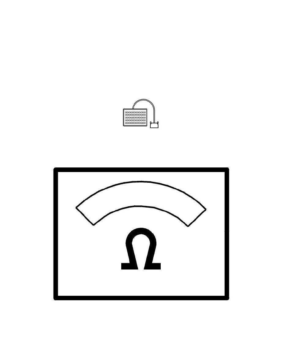
Measure the resistance at the connector between terminals #3 and #5. The resistance must be 120 ohms.
Note! Take care that you measure directly at the connector so that it is not damaged.
If the resistance is 0 ohms between the terminals, there short-circuit somewhere in the bus system.
Other information:
-
To connect the breakout box to the upper electronic module, see Connecting the breakout box See: Body and Frame/Body Control
Systems/Testing and Inspection/Pinout Values and Diagnostic Parameters/Connecting the Breakout Box
-
For further information about the connectors and bus cable, see the wiring diagram.
ohms
Is the resistance 0?
