
XC70 AWD L6-3.2L VIN 98 B6324S (2009)
The engine speed (rpm) sensor provides the engine control module (ECM) with information about the speed and position of the crankshaft. The engine
control module (ECM) is able to use the signal from the engine speed (rpm) sensor to determine when a piston is approaching top dead center.
The signal from the engine speed (rpm) sensor is also used to check the engine for misfires. For further information, see: Misfire diagnostic See:
Powertrain Management/Computers and Control Systems/Description and Operation/Misfire Diagnostic
The impulse sensor is located on the engine's flywheel side, pointing forward. The sensor is inductive with permanent magnet. When the flywheel/drive
flange plate passes the impulse sensor, an alternating voltage is induced in the sensor. The generated voltage and frequency increase when the engine
speed increases.
The signal varies between 0.1-100 V depending on the engine speed (rpm).
The Engine Control Module (ECM) is able to determine the engine speed (rpm) by counting the number of holes per time unit. When the reference
position passes the engine speed (rpm) sensor, the voltage and frequency drop momentarily to zero, even though the engine is still running. This allows
the engine control module (ECM) to determine the position of the crankshaft.
If the signal from the engine speed (rpm) sensor is incorrect or missing, the control module will use signals from the camshaft position (CMP) sensor.
The engine speed sensor can be diagnosed by the engine control module (ECM) and the sensor signal (engine speed) can be read out.
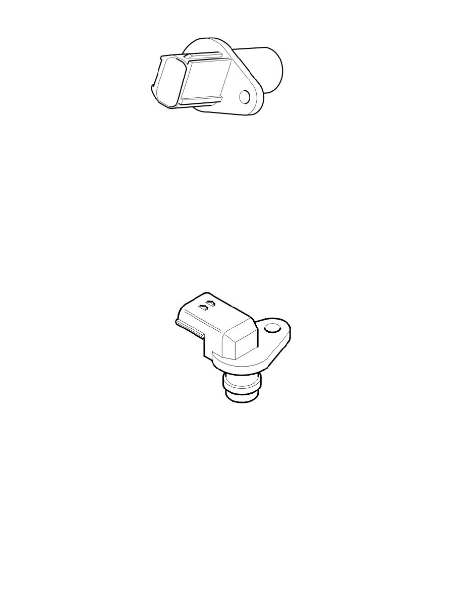
Camshaft position (CMP) sensor
The function of the camshaft position (CMP) sensor is to detect the flanks of the camshaft rotor. The signal from the sensor is used by the engine control
module (ECM) to determine the angle of the camshaft.
Each camshaft is divided into a number of flanks (segments) per camshaft revolution. A pulse wheel on the camshaft consisting of teeth (the teeth are
positioned by each flank) is used by the camshaft position sensor (CMP) to detect the flanks and the position of the camshaft.
In the event of misfire or engine knock, the control module is able to determine which cylinder is misfiring or knocking using the camshaft position
(CMP) sensor's signal. Also see "Design, Knock sensor and Design, Engine speed sensor".
Data about the camshaft position is used during camshaft control (CVVT). See: Function See: Powertrain Management/Computers and Control
Systems/Description and Operation/Engine Control Module (ECM)/Function
The sensor, which is a magnetic resistor with a permanent magnet, is grounded in the control module and supplied with 5 V from the control module.
When one of the teeth on the camshaft pulse wheel passes the camshaft position (CMP) sensor, a signal is transmitted to the control module from the
camshaft position (CMP) sensor. The signal varies between 0 and 5 V and is high when a tooth is in contact with the camshaft position (CMP) sensor
and low when the tooth leaves the camshaft position (CMP) sensor.
There is camshaft position (CMP) sensor for each camshaft.
The camshaft sensors are located by the camshafts on the engine's left side, closest to the flywheel.
The engine control module (ECM) can diagnose the camshaft position (CMP) sensors.
Knock sensor (KS)