
XC90 L5-2.5L Turbo VIN 59 B5254T2 (2004)
Apply liquid gasket 11 61 059 to the intermediate section. The surface must be completely covered without any excess. Use roller 951 2767 Roller See:
Tools and Equipment/951 2767 Roller
Thoroughly lubricate all the bearing shells and the surface of the axial bearing.
Tightening the intermediate section
Install the two old screws for the flywheel and carrier plate at the rear edge of the crankshaft.
Lift these and the front of the crankshaft.
Carefully position the crankshaft in the block.
The crankshaft must not be turned before the intermediate section has been torque tightened. Position the intermediate section.
Lubricate and install all the screws.
Note! Use new M10 screws.
Install the intermediate section and the screws on the exhaust side at bearing recesses 2 and 5.
Caution! The M8-screws on the exhaust side are two different lengths.
Pull down the intermediate section.
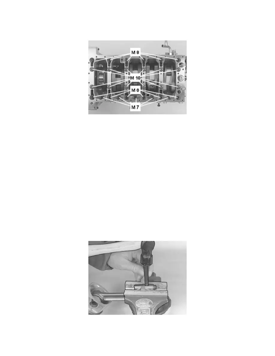
Tighten the screws in the following order:
1. All M10 screws.20 Nm
2. All M10 screws.45 Nm
3. All M8 screws.24 Nm
4. All M7 screws.17 Nm
5. Angle-tighten all M10 screws.90°
Tighten the screws in sequence from the center and outwards.
Marking the connecting rod (where applicable)
Assemble the connecting rod. Check that the cover is facing the correct direction. Tighten to 20 Nm.
Secure the large end of the connecting rod in a vise with soft jaws (copper or aluminum).
Mark both halves with the cylinder number. Use a center punch or number punch.
The bearing shell with the black color coding on the side must be installed in the connecting rod.