
XC90 L5-2.5L Turbo VIN 59 B5254T2 (2004)
The manifold absolute pressure (MAP) sensor detects the pressure in the intake manifold downstream of the charge air cooler (CAC). On 6 cylinder
turbocharged engines and B5254T2/-T4, the temperature of the intake air is also detected.
Pressure sensor
The signal from the sensor is primarily used by the engine control module (ECM) to check that the correct boost pressure is reached. The boost pressure
is governed by the turbocharger (TC) control valve.
The sensor, which is a piezo resistor, is grounded in the control module and supplied with 5 V from the control module.
The resistance in the sensor changes depending on the pressure in the intake manifold, giving a signal of 0 -5 V. Low pressure results in low voltage,
high pressure in high voltage.
Intake temperature
The temperature sensor detects the temperature of the intake air after the charge air cooler (CAC). This data is used by the engine control module (ECM)
to calculate the boost pressure control (turbocharger (TC) and to calculate the injection period. The control module also controls certain diagnostic
functions using the signal from the temperature sensor.
The sensor, which is an NTC resistor, is grounded in the control module and supplied with power (signal) from the control module.
The resistance in the sensor changes according to the temperature of the intake air. This provides the control module with a signal of between 0-5 V. The
lower the temperature the higher the voltage (high resistance). A high temperature results in low voltage (low resistance).
The engine control module (ECM) can diagnose the manifold absolute pressure sensor. The sensor signal can be read using VIDA.
The manifold absolute pressure (MAP) sensor is in the intake hose for the throttle body (TB).
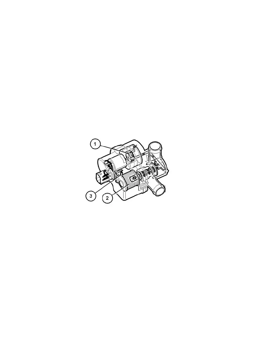
Leak diagnostic unit (certain markets only)
The function of the leak diagnostic unit is to pressurize the fuel tank system during leak diagnostics.
The leak diagnostic unit consists of a plastic housing with:
1. electrical air pump
2. a valve/solenoid which governs the air flow in the unit
3. a heater element (PTC resistor) which warms up the pump.
The electrical pump, valve and heater element in the unit are supplied with voltage by the system relay. The pump, valve and heater element are
grounded (control) in the engine control module (ECM).
Note! On model years, 2002-2004 the heating element was controlled by the Central electronic module (CEM), but on request from the Engine
control module (ECM).
During leak diagnostics the pump in the leak diagnostic unit starts. The valve in the unit is operated by the engine control module (ECM) by grounding
the different circuits internally in the engine control module (ECM).
The Engine control module (ECM) checks the fuel tanks system for leaks by pressurizing the system and at the same time monitoring a number of
relevant parameters. Also see: Leak diagnostics (certain markets only) See: Description and Operation/Leak Diagnostics (Certain Markets Only)
The engine control module (ECM) can diagnose the leak diagnostic unit.
The valve in the leak diagnostic unit can be activated.
The leak diagnostic unit is at the upper front edge of the fuel tank.
Part 2
Design (Continued)
Outside temperature sensor