
XC90 L5-2.5L Turbo VIN 59 B5254T2 (2004)
The outside temperature sensor detects the temperature in the surrounding air. The signal is used by the engine control module (ECM) as a substitute
value in the event of a fault in certain components or functions and to control certain diagnostic functions.
The sensor is a negative temperature coefficient (NTC) type which is supplied with power from the control module (signal) and is grounded in the
control module.
The resistance in the sensor, which provides a signal between 0-5 V, changes depending on the outside temperature. Low temperatures produce high
voltage (high resistance), high temperatures produce low voltage (low resistance).
The outside temperature sensor is positioned in the left door mirror.
The engine control module (ECM) can diagnose the outside temperature sensor. The sensor value can be read off using VIDA.
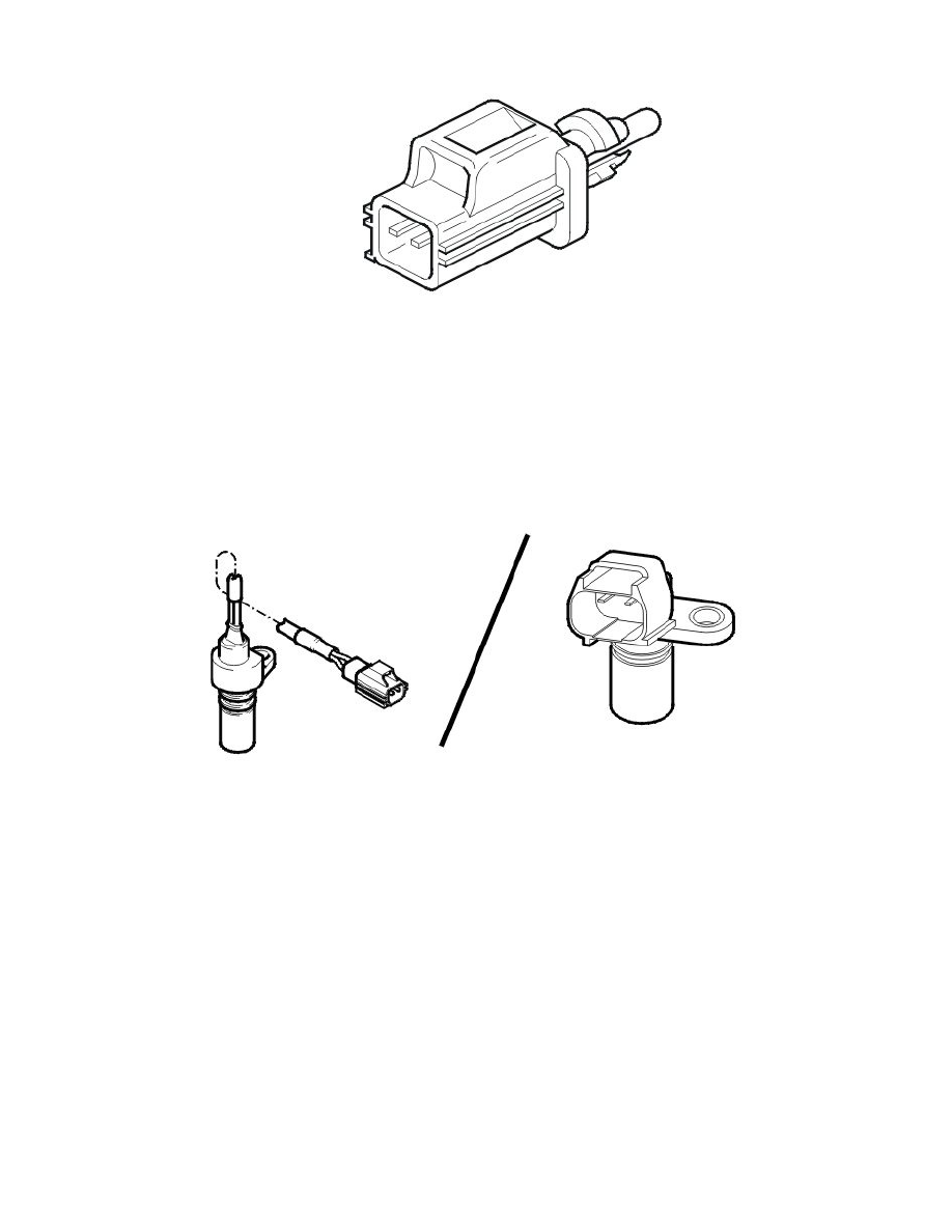
Engine speed (RPM) sensor
The engine speed (RPM) sensor provides the Engine Control Module (ECM) with information about the speed and position of the crankshaft. The
Engine Control Module (ECM) is able to use the signal from the engine speed (RPM) sensor to determine when a piston is approaching top dead center
(TDC). However it is unable to use the signal from the engine speed (RPM) sensor to determine whether the piston is in the combustion stroke or
whether the exhaust valve is open (exhaust stroke). The signal from the camshaft position (CMP) sensor is also required to determine the operating cycle
of the engine.
The signal from the engine speed (RPM) sensor is also used to check the engine for misfires. For further information, see Misfire diagnostics See:
Description and Operation/Misfire Diagnostics.
Cars with manual transmissions have a series of holes drilled in the periphery of the flywheel. Cars with automatic transmissions have a steel ring with
punched holes. This steel ring is welded to the edge of the carrier plate. In both cases, there is 6° between each hole. This arrangement creates a hole for
each tooth. There are 360° in one revolution. 6° between each hole means that there are 60 holes. However one hole is not drilled/punched, to create a
reference position (tooth) for the crankshaft. This reference position is 72° before the top dead center (TDC) of cylinder 1 on a 5 cylinder engine.
The engine speed (RPM) sensor is at the rear of the engine above the flywheel.
The sensor is inductive with a permanent magnet. An alternating current is induced in the sensor when the flywheel/carrier plate passes the engine speed
(RPM) sensor. The generated voltage and frequency increases with the engine speed (rpm). The signal varies between 0.1-100 V depending on the
engine speed (RPM).
The Engine Control Module (ECM) is able to determine the engine speed (RPM) by counting the number of holes per time unit. When the reference
tooth passes the engine speed (RPM) sensor, the voltage and frequency drop momentarily to zero, even though the engine is still running. This allows the
engine control module (ECM) to determine the position of the crankshaft.
The following applies to model year 2002 onwards:
If the signal from the engine speed (RPM) sensor is incorrect or missing, the control module will use the signals from the camshaft position (CMP)
sensor, on the condition that the position of the camshaft has been adapted and the car can be driven if there is no signal.