
XC90 L5-2.5L Turbo VIN 59 B5254T2 (2004)
Information Bus: Description and Operation
LIN - Local Interconnect Network
Network
Network
General
Increasing demands on functionality have made the electrical system in vehicles increasingly complex. By using a network with serial communications
between the different control modules several functions can be controlled and monitored using fewer cables.
Example of networks using serial communications are CAN and IN.
IN is an acronym for Local Interconnect Network and has been jointly developed as a common standard by a number of different automotive
manufacturers.
The concept involves the exchange of information, via serial communications with a single wire, between control modules where the same performance
as provided by a CAN network is not needed.
IN is usually used as a communications line between control modules on the CAN network and minor nodes, such as regulators and advanced sensors.
The number of control modules that communicate via LIN is dependent on the vehicle model and the level of equipment.
The difference between CAN and LIN is that the CAN network is routed throughout the entire vehicle. Whereas LIN is usually used in smaller separate
networks where the transfer speed and performance is not so highly prioritized. See the wiring diagram for the vehicle model in question for
topographical differences between LIN and CAN.
Advantages of a network
Instead of using a single wire for each function, serial communications over a network make it possible for hundreds of signals and functions to be
activated, controlled or read via the same wire.
Using a network it is even easier to adapt the system to customers and markets.
In relation to the number of functions and connected components the length of the wiring is short and the electrical system is more service friendly when
based on a network instead of direct connection.
Network Structure
Network structure
General
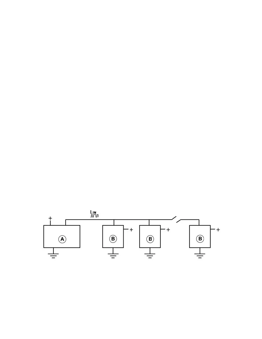
A = Master node
B = Slave node
The network is made up of a number of control modules connected to each other via a communications wire. The control modules are voltage fed and
ground individually and exchange information in an optional direction via the communication wiring.
In event of a failure on the communication wiring, the control modules will not be able to communicate with the other control modules located after the
failure. However, the control modules located before the failure can still communicate.
On a LIN bus there is always one control module that is the main control module (a.k.a. master node). All other control modules on the same LIN bus are
slave nodes.
Terminating resistor