
XC90 L5-2.5L Turbo VIN 59 B5254T2 (2004)
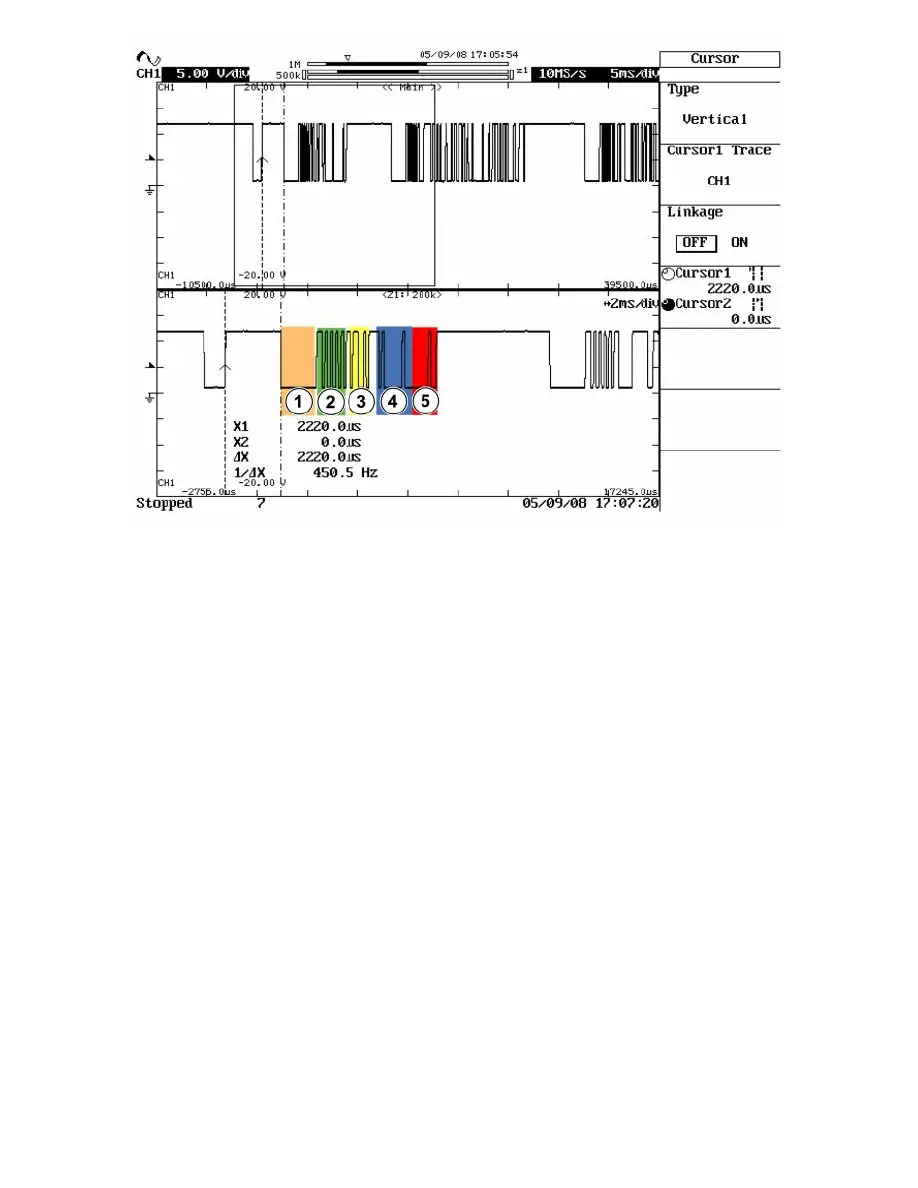
If you have access to an oscilloscope and measure on the LIN bus, a start-up procedure with subsequent communication can appear as illustrated in the
figure above.
The lower curve is a magnified section of the upper curve.
In the upper curve you first see the LIN bus in sleep mode with the subsequent message. This is followed by several messages.
The numbers in the different fields correspond to the parts of the message described in the list above.
In the figure you can see, among others, that the sleep voltage on the LIN bus is approximately 13 V and that the voltage drops to approximately 1 V
during communication.
Note! The figure above is only one example of how messages on the LIN network can appear.
Error Management In the Local Interconnect Network (IN)
Error management in the Local Interconnect Network (IN)
Electrical faults
The communication circuits in the LIN control modules cannot detect electrical faults on the wire. However the master node continuously reads back the
last message it sent itself to check that it has been sent correctly over the LIN bus.
Should the master node discover that the message last read back is incorrect, for example if the signal wire has been short-circuited to voltage or ground,
the master node can set the diagnostic trouble code (DTC) denoting the message has not been sent correctly.
Communication failure
The master node on a LIN bus sends out messages at specific time intervals.
The master node on the LIN bus in question knows which type of response that a particular slave node shall send back for a specific message sent from
the master node. If the master mode does not receive this response, it can set the diagnostic trouble code for failed communication with the slave node in
question.
Faults discovered by slave nodes
Control modules that use LIN communication can have integrated diagnostics exactly as the control modules on CAN. However, it is the Master node to
which the slave node is connected that stores the diagnostic trouble codes for faults that the slave node discovers.
Information about discovered faults in the slave nodes is sent in the messages to the master node.
Each slave node on a LIN bus can be seen as an extension of the master node's own connections. In most cases it is also the master node that makes
evaluations whether the diagnostic trouble code (DTC) can be set or not.