
XC90 L5-2.5L Turbo VIN 59 B5254T2 (2004)
The transmission control module (TCM) also uses this data for its gear shift calculations. This data is transmitted to the transmission control module
(TCM) from the engine control module (ECM) via the high speed side of the Controller area network (CAN).
The mass air flow (MAF) sensor consists of a plastic housing with connectors, test electronics and an aluminum heat sink. The test electronics in the
mass air flow (MAF) sensor consist of a hot film comprised of four resistors. The hot film is cooled by the air flow to the engine.
The mass air flow (MAF) sensor is supplied with battery voltage by the system relay and is grounded in the engine control module (ECM). The signal
from the sensor is analogue and varies between approximately 1-5 V depending on the air mass. Low air flow (low mass) results in low voltage, high air
flow (high mass) gives high voltage. No air flow gives a reading of approximately 1 V.
Intake temperature
The temperature sensor detects the temperature of the intake air after the charge air cooler (CAC). This data is used by the engine control module (ECM)
to calculate the boost pressure control (turbocharger (TC) and to calculate the injection period. The control module also controls certain diagnostic
functions using the signal from the temperature sensor.
The sensor, which is an NTC resistor, is grounded in the control module and supplied with power (signal) from the control module. The resistance in the
sensor changes according to the temperature of the intake air. This provides the control module with a signal of between 0-5 V. The lower the
temperature the higher the voltage (high resistance). A high temperature results in low voltage (low resistance).
The mass air flow (MAF) sensor is positioned between the air cleaner (ACL) housing and the intake manifold.
The engine control module (ECM) can diagnose the air mass and intake temperature of the mass air flow sensor. The signals can be read using VIDA.
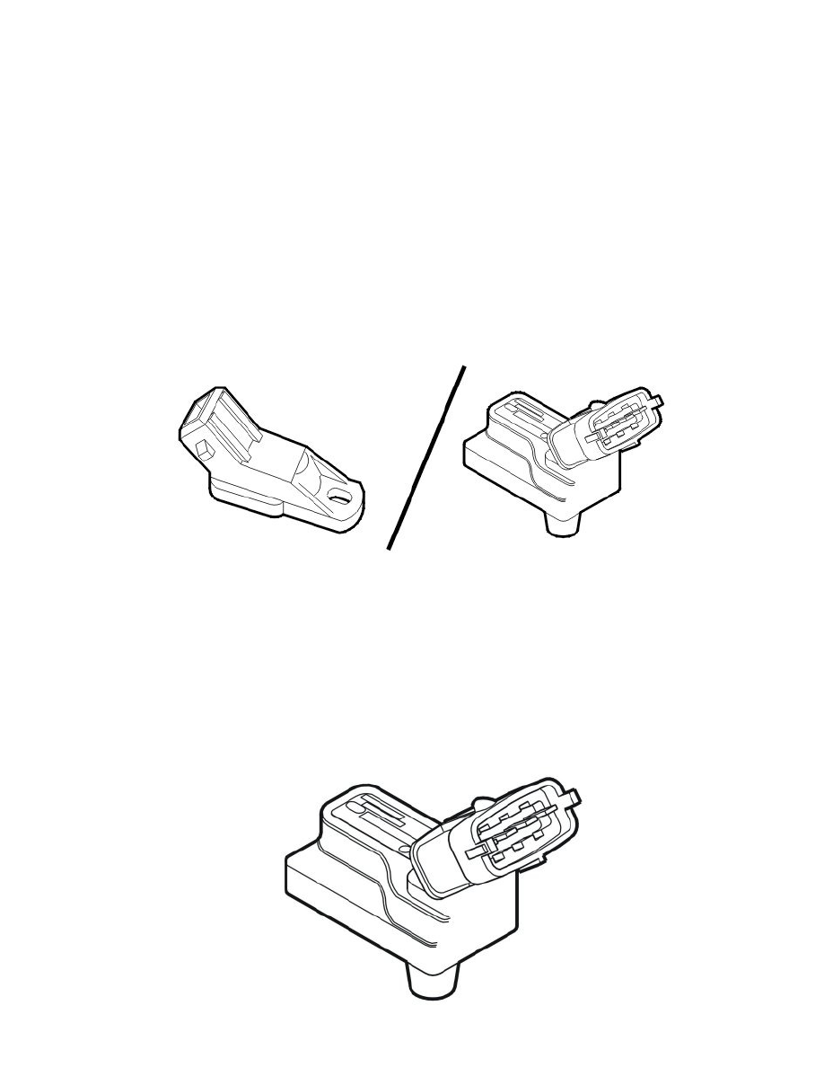
Manifold absolute pressure (MAP) sensor, intake (turbocharged engines only, 2002-2004)
The manifold absolute pressure (MAP) sensor detects the pressure in the intake manifold downstream of the charge air cooler (CAC). The signal from
the sensor is primarily used by the engine control module (ECM) to check that the correct boost pressure is reached. The boost pressure is governed by
the turbocharger (TC) control valve.
The sensor, which is a piezo resistor, is grounded in the control module and supplied with 5 V from the control module.
The resistance in the sensor changes depending on the pressure in the intake manifold, giving a signal of 0 -5 V. Low pressure results in low voltage,
high pressure in high voltage.
The engine control module (ECM) can diagnose the manifold absolute pressure sensor. The sensor signal can be read using VIDA.
The manifold absolute pressure (MAP) sensor is in the intake hose for the throttle body (TB).
Manifold absolute pressure (MAP) sensor, intake (turbocharged engines only, 2005-)