
XC90 L5-2.5L Turbo VIN 59 B5254T2 (2004)
network. First when communication takes place on this cable, the low and high-speed cables between the diagnostic outlet and central electronic
module (CEM) are connected to the rest of the network in the vehicle. This is controlled via a relay in the central electronic module (CEM). This
relay is only found on vehicles of model year -2004.
-
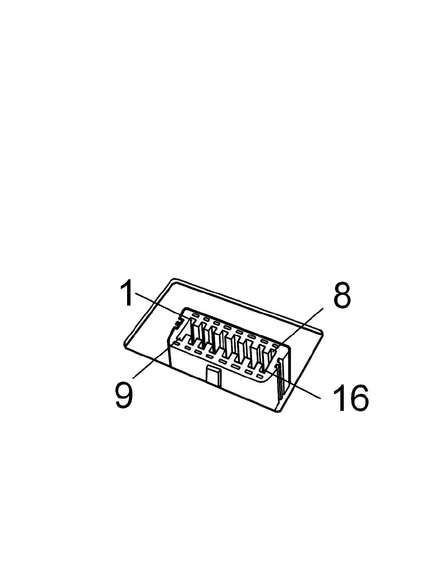
For communication problems with control units onthe high-speed network, check communication cables between diagnostic outlet #6/ #14 and
central electronic module (CEM) #B7/ #B8 for open circuit, short-circuit to ground and short-circuit to voltage according to references above.
-
For communication problems with control units onthe low-speed network, check communication cables between diagnostic outlet #3/#11 and
central electronic module (CEM) #B19/#B20 for open circuit, short-circuit to ground and short-circuit to voltage according to references above.
-
Also check the communication cables for the low and high-speed net between the central electronic module (CEM) and the other connected
control modules according to troubleshooting above.
Control modules
-
Check that the control module's voltage feed and ground connection are trouble-free.
Caution! If none of the above checks help, try reading out diagnostic trouble codes in the central electronic module (CEM). Done via VIDA
vehicle communication. A prerequisite for being able to communicate with the control modules in the car is that the central electronic module
(CEM) is active and can be communicated with. If communication is not possible with the central electronic module (CEM), check the voltage
feed and ground for the central electronic module (CEM).
VCT2000 and cable harness
-
Connect VCT2000 to the vehicle so that it is supplied with voltage. Test VCT2000 by selecting the system's self-test and VCT Test in the VIDA
main menu. If any malfunction is found according to the test, first replace the cable harness then the VCT2000, if the test still indicates a
malfunction.
-
If no malfunctions were found after troubleshooting according to above, try with a new cable harness and/or new VCT2000.
VIDA
-
If no malfunctions were found after troubleshooting according to above, try performing a complete system reset of VIDA.
Other information
-
Checking wiring and terminals See: Testing and Inspection/Component Tests and General Diagnostics/Checking Wiring and Terminals
Continue - FAULT FOUND
------------------------
Checking communication errors, car model V70 (-00), V70 XC and S70/C70
Hint: Test the communication with another corresponding vehicle to decide if the malfunction is in the vehicle or in VIDA/VCT/cable harness. If the
communication works on another vehicle, the malfunction is in the vehicle.
Hint: For current information about each circuit and signals, see wiring diagram and signal description for each system.
Diagnostic outlet
-
Check the voltage feed to diagnostic outlet #16. The voltage shall match battery voltage.
-
Check the cable for power ground and signal ground to diagnostic outlet #4 and #5.
Hint: When VCT2000 is connected to the diagnostic outlet (is supplied with voltage), the indicator diode shall be activated with a green light. Then the