
XC90 L5-2.5L Turbo VIN 59 B5254T2 (2004)
-
NOTE! Read through the whole installation instruction before starting the work.
-
The illustrations display the procedure in order of operation. The order of operation is repeated in the text section.
Cars equipped with SRS/SIPS (Airbag)
Warning! Extra care must be taken when working on cars equipped with SRS/SIPS air bags. This is important to prevent: 1. Personal injury
2. Damage to or malfunction of the SRS/SIPS system. Work on the SRS/SIPS systems or related components must be carried out by an
authorized Volvo workshop.
Is the car equipped with SRS/SIPS?
Cars with SRS are most easily recognized by the letters SRS on the steering wheel pad. If the car also has an airbag on the passenger side, the letters SRS
are embossed on the dashboard above the glove compartment. SIPS decals are located on the seat panels and the windscreen.
Do not damage the SRS wiring!
Do not trap, fray, pierce or damage the SRS wiring. SRS wiring has orange casing and/or is plaited.
Steering and front suspension
The contact reel in the SRS system can easily be damaged when working on the steering wheel, steering shaft or steering gear. Refer to the SRS service
information on carrying out such work. This is to prevent damage.
SRS warning lamp
If the SRS warning lamp lights after repairs have been carried out, take the car to an authorized Volvo workshop.
SRS collision sensor control module
S60/V70(00-)/S80
The collision sensor control module is located on the transmission tunnel in the centre console, beside the parking brake. The air bag inflation areas must
not be obstructed. Never place any objects, such as upholstery, within these areas. The panels must be able to open in the correct way and at the right
time.
WARNING!
The ignition must be in position "0" and the key removed from the ignition if any connector in the SRS system is to be disassembled. Then wait
at least five minutes. Then disconnect the battery negative lead before disassembling any of the connectors.
Relay kit fog tail lamp + relay kit positive power supply
Note! Kit illustration A applies when connecting the positive power supply function. Kit illustration B applies when connecting a fog tail lamp.
Preparatory work
Illustration A
Applies to the S60/S80
-
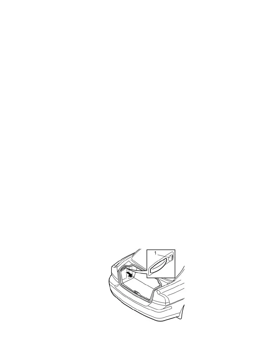
Turn the handle (1) on the left-hand side through 90°.
-
Fold the panel inwards to access the fusebox inside.