
XC90 L5-2.5L Turbo VIN 59 B5254T2 (2004)
Relay and fuse location, 11D
For the location of the relays and fuses, see: See: Power and Ground Distribution/Locations
1. Wiring diagram for relevant model year
2. Decals at both the integrated relay box and fusebox in the car
3. Pocket data book
4. Owner's Manual.
Installing the integrated relay/fusebox in the cargo compartment
Align the integrated relay/fusebox in the grooves in the bracket and press into place.
Install the left side panel in the cargo compartment.
Replacing the rear electronic module (REM)
The rear electronic module (REM) is a separate unit in the relay box in the cargo compartment.
Caution! New software can only be ordered when the control module is installed in the car. VIDA reads off the new control module identity
which is required to order the correct software.
Release the relay and fuse box. See Exposing the integrated relay/fusebox in the cargo compartment.
Removing the control module
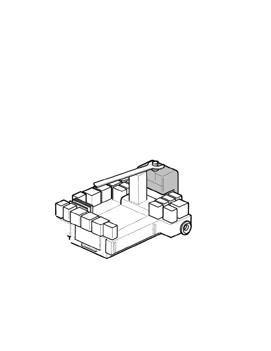
Unscrew the screw holding the connector so that it is free of its threads. Check that the screw is free with your fingers.
Disconnect the connector. Use an open spanner and a support. See the illustration.
Note! Do not damage the pins. Always check that the control module's and control module box's connectors do not have bent or damaged pins
or sleeves. This may have be the cause of the problem.