
XC90 2.5T AWD L5-2.5L Turbo VIN 59 B5254T2 (2003)
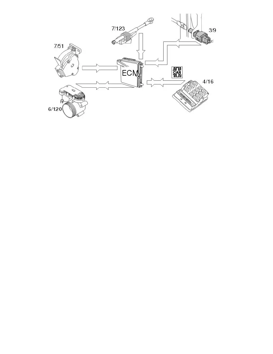
To ensure that the correct throttle angle is reached, the engine control module (ECM) controls the throttle shutter in the throttle unit (6/120), mainly
using the signal from:
-
accelerator pedal (AP) position sensor (7/51)
-
clutch pedal sensor (7/123)
-
stop lamp switch (3/9)
-
the throttle position (TP) sensor on the electronic throttle unit (6/120)
-
brake control module (BCM) (4/16), signal for the brake pedal sensor.
Additional signals and parameters are used to ensure optimum throttle control. For example there is compensation for the load from the air conditioning
(A/C) compressor, load from the transmission depending on the gear selected (automatic), engine temperature etc. In cars with Four-C (Continuously
Controlled Chassis Concept), the throttle characteristic changes depending on the driving mode selected.
The position of the throttle is measured by two potentiometers, in the throttle position (TP) sensor, which are on the throttle unit. These are connected, so
that potentiometer 1 produces a higher voltage as the throttle angle increases, while potentiometer 2 does the opposite.
In a combustion engine, the difference between the minimum and maximum airflow is considerable. The smaller air flows need more thorough
regulation, so the potentiometer signal from potentiometer 1 is amplified approximately 4 times in the engine control module (ECM) before it reaches the
Analog/Digital converter in the engine control module (ECM). This means that there are three, two real and one fictitious, input signals available to the
engine control module (ECM). These signals are used to determine the position of the throttle and to deploy the damper motor to the correct position. In
general the amplified signal is primarily used for small throttle angles (small air flows), which are desirable when a high degree of accuracy is required,
for idle air trim for example.
Because the signal is amplified, it reaches its maximum value as early as approximately a quarter of maximum deployment.
The engine control module (ECM) first uses the signal from potentiometer 1 to measure the throttle opening. The signal from potentiometer 2 is mainly
used to check that potentiometer 1 is functioning correctly. The engine control module (ECM) then uses the signal to calculate a throttle angle (actual
value). This is the actual throttle angle. The value for the actual throttle angle is used by those functions in the engine control module (ECM) which
depend on this information so that the throttle can be correctly regulated.
There is an adaptation (learning) in the engine control module (ECM) so that the control module can calculate how the damper motor needs to be
controlled. See "Adaptation of the throttle unit" below. This adaptation is carried out during manufacture of the car, when the engine control module
(ECM) deploys the throttle disc to the different positions and reads off and registers the actual values from the potentiometers.
The throttle angle is regulated so that the actual angle (actual value) is the same as the angle calculated by the engine control module (ECM) (desired
value). The engine control module (ECM) also uses the values that were stored during adaptation of the throttle angle, and the actual signals from the
potentiometers.
The damper motor is controlled by a power stage integrated in the engine control module (ECM) using a pulse width modulation (PWM) signal. The
torsion from the opening and return springs in the throttle unit is also used. If there is a fault in the engine control module (ECM) so that the throttle unit
cannot be operated or supplied with power, the springs in the throttle unit will turn the throttle disc to the limp home position (return position). This
return position gives a throttle angle large enough to allow the car to be driven to a workshop, although with considerably reduced driveablity.
Throttle angle
The throttle angle is usually gauged by potentiometer 1. For small angles the amplified signal is used to obtain a clearer signal. The engine control
module (ECM) also monitors the throttle unit signals from the potentiometers to check that they are plausible, that they are within the minimum and
maximum limits and that the signals correspond to the same throttle angle. If there is a difference in the signals, a fictitious throttle signal is calculated
from the load signal, the engine speed (rpm) and the prevailing conditions, particularly pressure and temperature.