
XC90 2.5T AWD L5-2.5L Turbo VIN 59 B5254T2 (2003)
The function of the accelerator pedal (AP) position sensor is to provide the engine control module (ECM) with information about the position of the
accelerator pedal. This data is used by the control module to deploy the shutter in the throttle unit to the correct angle.
The sensor consists of a plastic housing with two potentiometers, an Analog/Digital converter and circuits. The potentiometers are connected to a shaft
which is affected by the position of the accelerator pedal (AP). The resistance in the potentiometers changes with the position of the accelerator pedal
(AP).
The accelerator pedal (AP) position sensor transmits an analogue and a digital signal (pulse width modulated (PWM) signal) to the control module.
These signals indicate the position of the accelerator pedal (AP). The digital signal is generated by the sensors Analog/Digital converter.
The analog and digital signals are used at the same time by the control module to regulate the throttle shutter angle.
The sensor is supplied with 12 V by the system relay via a fuse and is grounded to the body.
The digital signal is also used in conjunction with the analog signal for accelerator pedal position sensor diagnostics. The accelerator pedal (AP) position
sensor signals can be read off using VIDA. A diagnostic trouble code (DTC) is stored if the engine control module (ECM) detects a difference between
the analog and digital signals. The engine control module (ECM) then uses a minimal value to ensure the function (limp home).
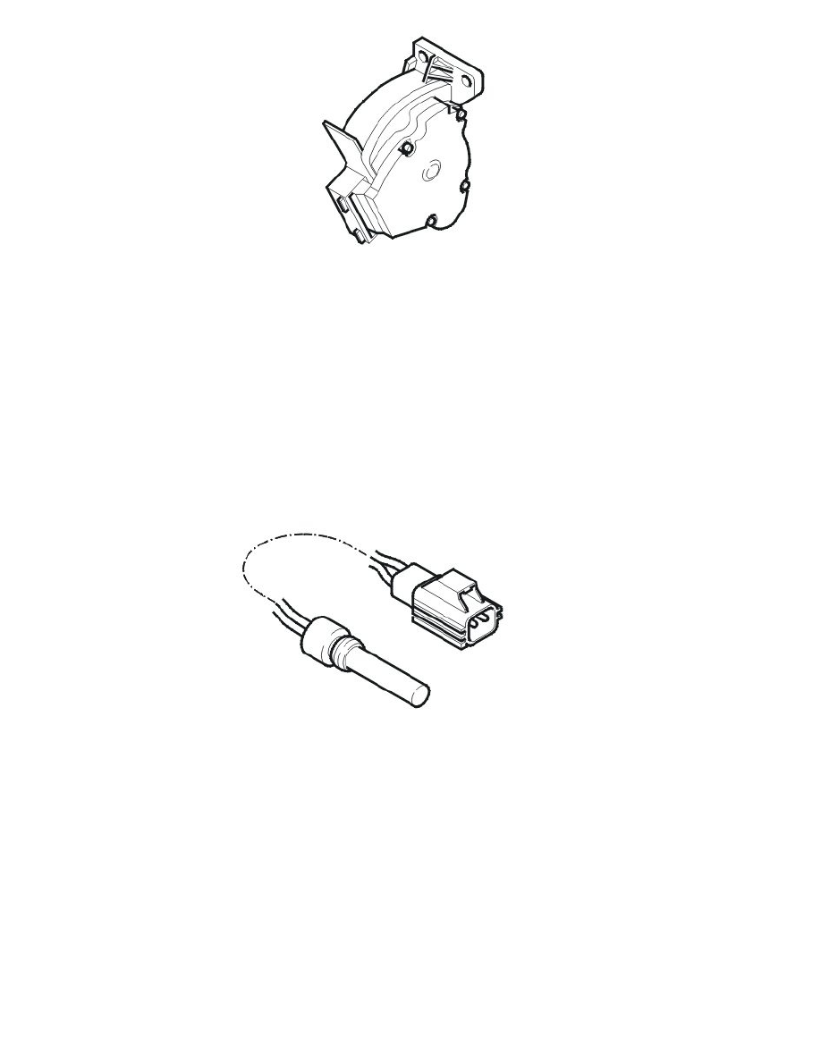
The accelerator pedal (AP) position sensor is located on the accelerator pedal bracket.
Engine coolant level sensor
The function of the engine coolant level sensor is to alert the driver if the engine coolant level in the expansion tank is too low.
The sensor is a magnetic reed switch, which is enclosed in a pipe on the bottom of the expansion tank. Around the pipe, on the inside of the expansion
tank is a float. This float contains a magnet. When the engine coolant level is above minimum, the float is too high in the tank to affect the switch.
However if the engine coolant level falls below the minimum level, the magnetic field acts on the switch.
The sensor is supplied with voltage (signal) from the Engine Control Module (ECM) and grounded in chassis. When the engine coolant level in the
expansion tank is over a certain level the circuit closes, which produces a low signal. When the engine coolant level is below a certain level the circuit is
opened by the engine coolant level sensor, which produces a high signal. When the engine control module (ECM) detects a high signal the information
about low engine coolant level is transmitted via the Controller area network (CAN) to the driver information module (DIM), which warns the driver.
Note! There are no functions controlled by the engine which are directly connected to the low coolant level warning lamp. The Engine Control
Module (ECM) only transfers the signal which is used by the Driver Information Module (DIM).
The following applies from model year 2005-
The signal of the engine coolant level sensor can be read using VIDA.
The engine control module (ECM) cannot diagnose the engine coolant level sensor.
Temperature sensor, intake (turbocharged engines only, 2002-2004)