
XC90 AWD L6-3.2L VIN 98 B6324S (2007)
-
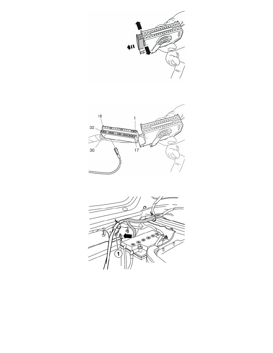
Carefully pry apart the sides of the connector holder in the ends so that the connector can pass by the retaining hooks.
-
Pull the connector out from the holder.
-
Connect a replacement part terminal (P/N 30656727) to position 30 in the connector.
-
Reinstall the connector in the holder and reinstall the whole unit in the fuse holder.
-
Connect ground lead (31-) to the relay with a conductor with cable terminal (P/N 970784) to the existing ground terminal (1) behind the battery.
Tighten the ground screw firmly.
Only applies if the brake lamp signal is to be connected to the electric brakes
-
Connect a replacement part terminal (P/N 30656647) to position 1 in the tow hitch wiring's gray connector on the trailer module (TRM). Splice it
with the cable for the brake lamp's input signal from the brake equipment, with a yellow butt connector (P/N 9130477).
-
Connect the electric brakes after the relay with a fuse, maximum 30A. Connect the electric brake output to the trailer connector via pin 3, spare
(see step 15).
The cables should have a minimum 4 mm cross-section if a 30A fuse is used.
The equipment will be supplied with power as long as the car has its ignition on.
Note! If the electric brakes are connected without relay control in accordance with above, then there is a risk that the car's battery will be