
XC90 AWD L6-3.2L VIN 98 B6324S (2007)
The evaporative emission system (EVAP) valve is used to open and close the connection between the EVAP canister and the intake manifold. The valve
controls the flow of hydro-carbons (fuel vapor) from the EVAP canister to the engine intake manifold using the vacuum in the intake manifold. This
ensures that hydro-carbons stored in the EVAP canister are used in the engine combustion process.
The valve is an electromagnetic valve and is powered from the system relay. When the valve needs to be opened, it is grounded internally in the engine
control module (ECM). The evaporative emission system (EVAP) valve is closed when in the standby position (open-circuit).
When the control module requests that the EVAP canister should be drained (the hydrocarbons stored in the canister should be released into the engine),
the control module deploys the evaporative emission system (EVAP) valve by grounding it. A pulse width modulation (PWM) signal is used to ground
the valve and to control the degree to which the valve will open. In this way, the drainage of the EVAP canister is matched to the volumetric efficiency of
the EVAP canister, the engine speed (RPM) and the engine load.
The evaporative emission system (EVAP) valve can be diagnosed by the engine control module (ECM) and can be activated.
The EVAP-valve is located by the intake manifold (by the electronic throttle module) on the front of the engine.
Leak diagnostic unit
The function of the leak diagnostic unit is to pressurize the fuel tank system during leak diagnostics and to open the fuel tank system to the surrounding
air during evaporative emissions control.
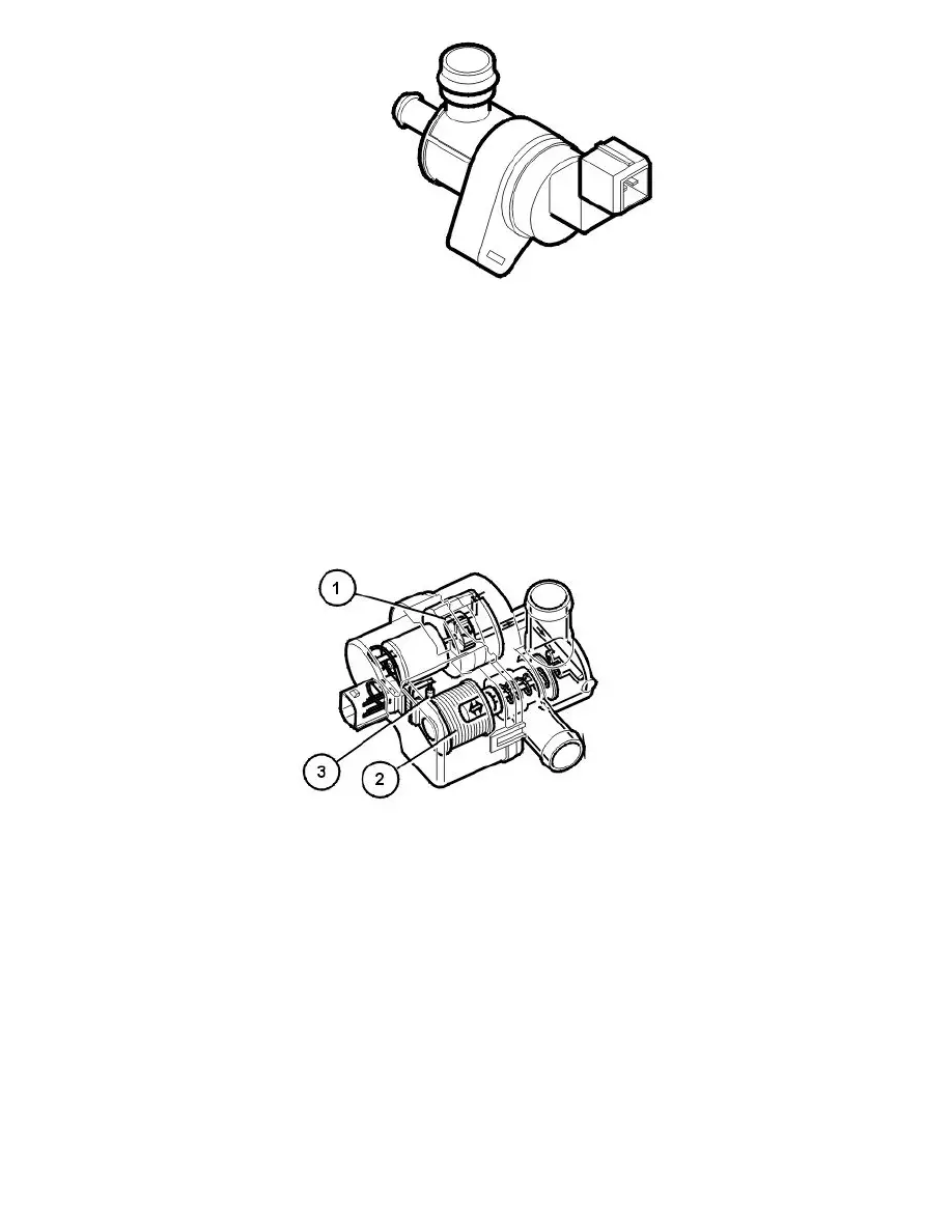
The leak diagnostic unit consists of a plastic housing with:
1. electrical air pump
2. a valve/solenoid which governs the air flow in the unit
3. a heater element (PTC resistor) which warms up the pump.
The electrical pump, valve and heater element in the unit are supplied with voltage by the system relay. The pump, valve and heater element are
grounded (control) in the engine control module (ECM).
During leak diagnostics the pump in the leak diagnostic unit starts. The valve in the unit is operated by the engine control module (ECM) by grounding
the different circuits internally in the engine control module (ECM). Operation depends on whether the diagnostic phase is checking for leakage or
checking the function of the diagnostic system. The engine control module (ECM) gauges the power consumption of the pump during pressurization. The
power consumption corresponds to a certain pressure in the fuel tank system. See also: Leak diagnostics (certain markets only) See: Powertrain
Management/Computers and Control Systems/Description and Operation/Leak Diagnostics (Certain Markets Only)
The engine control module (ECM) can diagnose the leak diagnostic unit.
The valve in the leak diagnostic unit can be activated and the power consumption of the pump can be read off.
The leak diagnostic unit is at the upper front edge of the fuel tank.
air conditioning (A/C) compressor.