
XC90 AWD L6-3.2L VIN 98 B6324S (2007)
The engine control module (ECM) calculates the desired fuel pressure. A signal is then transmitted to the fuel pump control module indicating the
desired fuel pressure. Serial communication between the engine control module (ECM) and the fuel pump control module is used to carry the signal. The
fuel pump control module then operates the fuel pump unit to obtain the desired pressure using a pulse width modulation voltage on the ground lead. The
fuel pump (FP) can be controlled steplessly by changing the pulse width modulation (PWM) signal. Only that pressure which is required at that specific
time will then be released to the fuel rail/injectors. The value of the pulse width modulation (PWM) signal is a measurement of the operational load of
the fuel pump (FP) (% duty, 100% = maximum pressure).
The engine control module (ECM) continuously monitors the fuel pressure using the signal from the fuel pressure sensor. This allows the desired fuel
pressure to be reached, and if necessary a signal is transmitted to the fuel pump control module requesting that the fuel pressure is adjusted.
The engine control module (ECM) attempts too obtain a constant fuel pressure (approximately 380kPa relative to atmospheric pressure with the engine
running).
By-pass valve
When the injectors close when the pressure is too great (during engine braking for example) there is a pressure peak. The by-pass valve in the fuel pump
(FP) is used to even out the pressure peak. The opening pressure of the valve is approximately 650 kPa.
The by-pass valve also functions as a non-return valve, ensuring that the fuel pressure in the system is maintained when the engine is switched off.
There is high pressure before the engine is started. This high pressure means that the valve in the by-pass valve opens and the system is "flushed".
Passive safety
For safety reasons, the engine control module (ECM) shuts off the fuel pump (FP) if the supplemental restraint system module (SRS) detects a collision.
Knock control
Knock occurs in the combustion chamber when the fuel and air mixture self ignites. This can occur either before or after the spark plug has produced an
ignition spark. In both cases the gas in two or more places ignites in the combustion chamber.
This results in an extremely fast combustion process with flames from several directions. When these flames collide, the pressure in the cylinder
increases rapidly and there is a mechanical knocking sound.
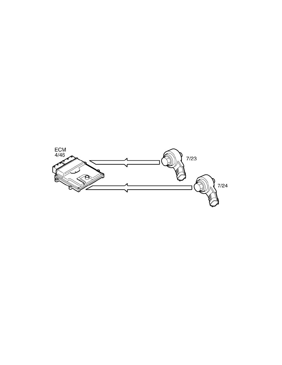
If any cylinder knocks, then certain types of vibrations in the engine block. These vibrations are transmitted to the knock sensors (7/23-24), which are
bolted in the engine block.
One knock sensor detects knock on cylinders 1, 2, 3. The other knock sensor detects knock on cylinders 4, 5, and 6.
The mechanical stress generated in the knock sensors' piezo-electric materials result in generation of a voltage. The Engine control module (ECM) (4/46)
can then, using the camshaft sensors (7/172-173) and the impulse sensor (7/25), decide which cylinder is knocking.
The knock sensors (KS) also interpret a proportion of normal engine sound. The control module is able to recognize the vibrations which correspond to
knocking by filtering, amplifying and using software to evaluate the signal.
If the knock sensors (KS) detect knocking in the engine above a certain threshold value, the ignition timing is first retarded and then the fuel/air mixture
is enriched to eliminate knocking.
Ignition control