XC90 AWD V8-4.4L VIN 85 B8444S (2005)

The status indicates whether the -3 db switch was activated or not.
on = activated
off = not activated
Time, value
The value displays the time that has passed since the diagnostic trouble code (DTC) was stored.
Connecting the Breakout Box, Audio Module (AUD)
Connecting the breakout box
Special tools:
951 1463 Adapter 22-16-14 pin See: Tools and Equipment/951 1463 Adapter 22-16-14 Pin
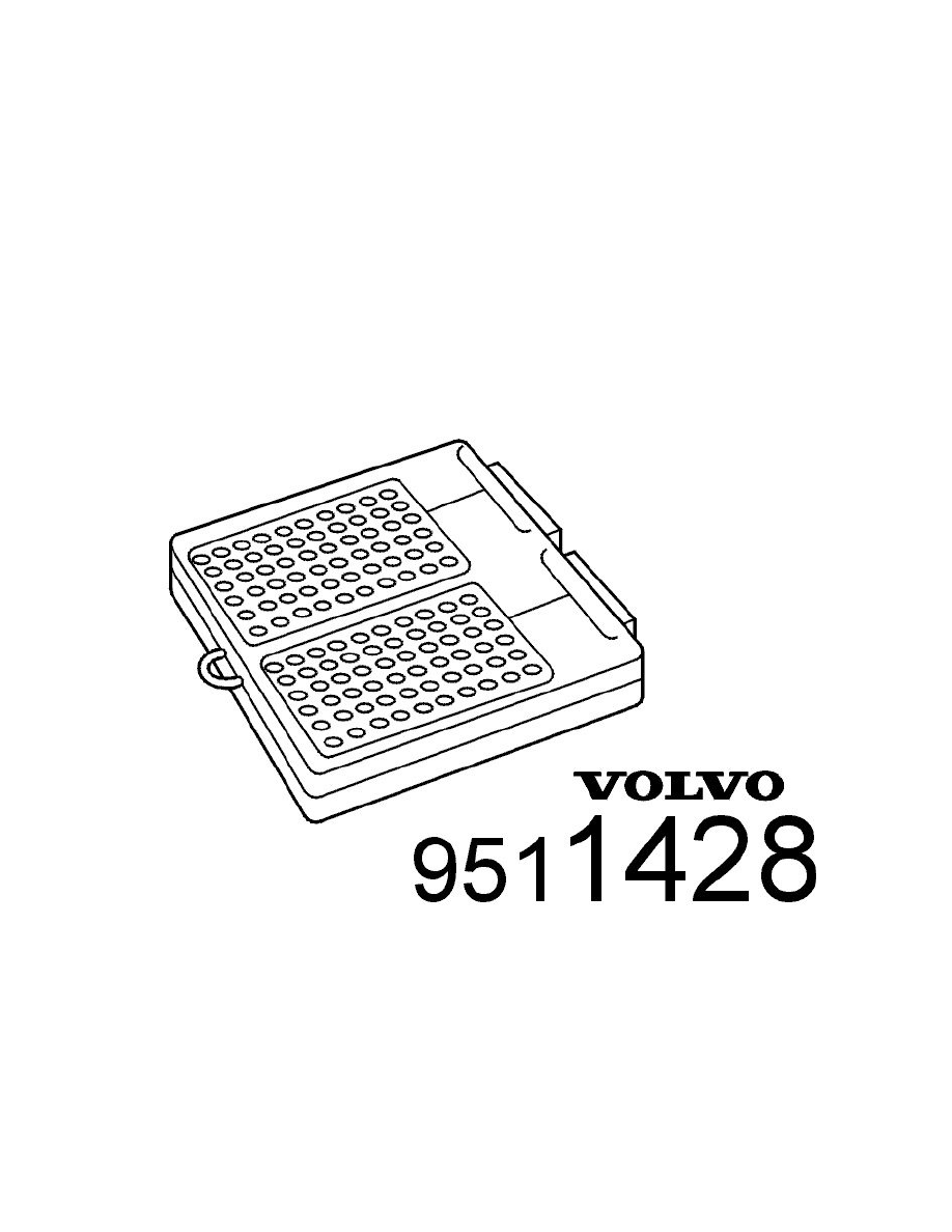
951 1428 Breakout box See: Tools and Equipment/951 1428 Breakout Box
951 1507 Adapter 12-12-8-4-2 Pin See: Tools and Equipment/951 1507 Adapter 12-12-8-4-2 Pin
951 2888 16-pin AUD adapter See: Tools and Equipment/951 2888 16-Pin AUD Adapter
Connecting the breakout box
-
Ignition off
-
Expose the audio module (AUD)
-
Remove the fuse for the audio module (AUD).
Connect adapter951 1463 Adapter 22-16-14 pin See: Tools and Equipment/951 1463 Adapter 22-16-14 Pin to the control module connector (wiring
side). Connect breakout box951 1428 Breakout box See: Tools and Equipment/951 1428 Breakout Box to the adapter. Audio module (AUD) terminals
#C1-#C22 correspond to terminals #1-#22 on the breakout box. Connect adapter951 1507 Adapter 12-12-8-4-2 Pin See: Tools and Equipment/951 1507
Adapter 12-12-8-4-2 Pin to the control module connector (wiring side). Connect breakout box951 1428 Breakout box See: Tools and Equipment/951
1428 Breakout Box to the adapter. Audio module (AUD) terminals #A1-#A2 correspond to terminals #45-#46 on the breakout box. Connect adapter951
2888 16-pin AUD adapter See: Tools and Equipment/951 2888 16-Pin AUD Adapter to the control module connector. Connect breakout box951 1428
Breakout box See: Tools and Equipment/951 1428 Breakout Box to the adapter. Audio module (AUD) terminals #B1-#B16 correspond to terminals
#1-#16 on the breakout box.
The breakout box is designed to facilitate reading off the control module input and output signals when the control module is connected and cable and
component resistance when the control module is disconnected. The use of a breakout box reduces the risk of accidental short-circuited cables and
damage to the connector pins
