
XC90 AWD V8-4.4L VIN 85 B8444S (2005)
Remove the screws.
Use a 6 mm torx external socket.
Carefully pull the control module down so that the terminal pin on the control module comes loose inside the ABS modulator.
Continue pulling the control module down towards the brake lines and lift it out.
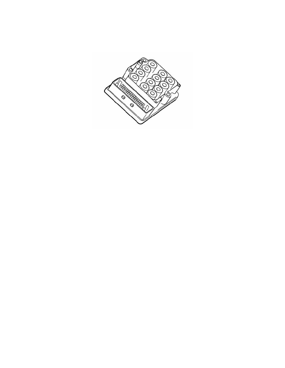
Installing the control module
Check:
-
the control module is correct (compare to the old one)
-
that none of the pins on the connector are damaged
-
that there are no contaminants on the mating surfaces between the control module and the ABS hydraulic modulator
-
that no parts of the old control module seals remain on the old ABS hydraulic modulator valves.
Position the control module on the brake lines.
Center the control module with the ABS modulator valves so that the terminal pins are correctly positioned in the modulator.
Press the control module up so that the terminal pins connect.
Install:
-
the screws. Tighten to 1.8 Nm.
-
the connector on the control module. Lock the connector.
Installing the integrated relay / fusebox
Install the box in its mounting.
Install:
-
the cable harness
-
the connector
-
the 2 screws in the mounting. Tighten to 10 Nm)
-
the 2 power supply cables
-
the nut for the mounting for the power supply cables.
Installing the air cleaner (ACL) housing
Press the air cleaner (ACL) housing into place.
Install the air hoses and the connector.
Finishing
Warning! No ABS, stability and traction control functions are available when there is communication with the Brake control module (BCM)
(Volvo Diagnostics are activated). ABS warning lamp flashes for as long as the diagnostics are activated. To cancel the diagnostics before test
driving the vehicle, the ignition must be switched off!