
XC90 AWD V8-4.4L VIN 85 B8444S (2005)
The mass air flow (MAF) sensor gauges the air mass sucked into the engine. It continuously transmits signals to the engine control module (ECM) about
the mass of the intake air. This data is used by the engine control module (ECM) to calculate:
-
the injection period
-
the fuel pressure
-
the ignition timing
-
the engine load.
The transmission control module (TCM) also uses this data for its gear shift calculations. This data is transmitted to the transmission control module
(TCM) from the engine control module (ECM) via the high speed side of the Controller area network (CAN).
The mass air flow (MAF) sensor is a hot wire type. Unlike other hot wire types, the mass air flow sensor in the Denso system uses a hot wire which has a
ceramic casing. This eliminates the need for a clean burn function.
The mass air flow (MAF) sensor is supplied with battery voltage by the system relay and is grounded in the engine control module (ECM). The signal
from the sensor is analog and varies between approximately between 0.5 - 4.5 V. Low air flow (low mass) results in low voltage, high air flow (high
mass) gives high voltage.
The mass air flow (MAF) sensor can be diagnosed by the engine control module (ECM) and the sensor signal can be read off.
Intake air temperature (IAT) sensor
The temperature sensor checks the temperature of the intake air in the intake manifold. This data is used by the engine control module (ECM) to
calculate injection period. The control module also controls certain diagnostic functions using the signal from the temperature sensor.
The sensor, which is an NTC resistor, is grounded in the control module and supplied with power (signal) from the control module.
The resistance in the sensor changes according to the intake air temperature. This provides the control module with a signal of between 0.5 - 5 V. The
lower the temperature the higher the voltage (high resistance). A high temperature results in low voltage (low resistance).
The temperature sensor can be diagnosed by the engine control module (ECM) and the sensor signal can be read off.
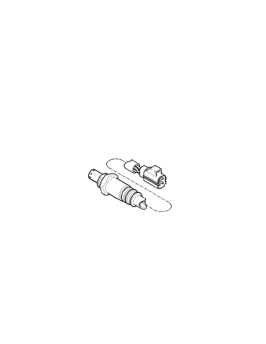
Heated oxygen sensors (HO2S)
Front heated oxygen sensor (HO2S)
Caution! The air lines for the heated oxygen sensors (HO2S) must not be trapped or damaged in any way. The connectors for the heated
oxygen sensors (HO2S) must not be greased under any circumstances. The oil in the grease would disrupt the reference air and the function of
the heated oxygen sensors (HO2S).
Front heated oxygen sensor (HO2S) is used to provide the engine control module (ECM) with information about the remaining oxygen content of the
exhaust gases before the three-way catalytic converter (TWC). This is so that the engine control module (ECM) can continually check the combustion so
that lambda = 1 is achieved. lambda = 1 is the ideal fuel-air ratio, with 14.7 kg air per 1 kg fuel.
The heated oxygen sensor (HO2S) uses current control and its signal characteristic is linear. With a linear signal characteristic, the amplitude of the
signal curve is low when changing the oxygen content in the exhaust gases. The probe consists of a preheating element (see "Pre-heating heated oxygen
sensors (HO2S)") and the actual lambda sensor. The lambda sensor is an oxygen sensitive ceramic body consisting of zirconium oxide. The control
module supplies power to the ceramic body, which reacts to the oxygen content of the exhaust gases. This in turn affects the signal to the engine control
module (ECM). In order to determine the oxygen content in the exhaust pipe, the heated oxygen sensor (HO2S) needs reference air from the surrounding
air. This reference air reaches the heated oxygen sensor (HO2S) via the air lines.
Caution! The air lines for the heated oxygen sensors (HO2S) must not be trapped or damaged in any way. The connectors for the heated
oxygen sensors (HO2S) must not be greased under any circumstances. The oil in the grease would disrupt the reference air and the function of
the heated oxygen sensors (HO2S).
There are two front heated oxygen sensors; one for bank 1 and one for bank 2.
Bank 1 (front cylinder row); cylinders 1, 3, 5 and 7.
Bank 2 (rear cylinder row, closest to the passenger compartment); cylinders 2, 4, 6 and 8.