
XC90 AWD V8-4.4L VIN 85 B8444S (2005)
See: Powertrain Management/Computers and Control Systems/Description and Operation/Engine Control Module (ECM)/Function
An oil filter is mounted at the intake channel for the valves to prevent oil contaminants from affecting the function of the reset valves.
The system relay supplies the reset valve with voltage via a fuse. The valve is grounded (control) in the engine control module (ECM). When the valve is
grounded using a pulse width modulation (PWM) signal, the oil flow in the valve can be regulated to the different chambers in the continuous variable
valve timing (CVVT) unit at variable rates. This allows the cam timing to be changed precisely and steplessly.
It is important not to mix up the pipes for the valves when removing/installing the reset valve camshaft.
The engine control module (ECM) can diagnose the camshaft reset valve.
The valves are on the cylinder head above the camshafts. There are four reset valves, two for the inlet camshaft and two for the exhaust camshaft.
Evaporative emission system (EVAP) valve
The evaporative emission system (EVAP) valve is used to open and close the connection between the EVAP canister and the intake manifold. The valve
controls the flow of hydro-carbons (fuel vapor) from the EVAP canister to the engine intake manifold using the vacuum in the intake manifold. This
ensures that hydro-carbons stored in the EVAP canister are used in the engine combustion process.
The valve is an electromagnetic valve and is powered from the system relay. When the valve needs to be opened, it is grounded internally in the engine
control module (ECM). The evaporative emission system (EVAP) valve is closed when in the standby position (open-circuit).
When the control module requests that the EVAP canister should be drained (the hydrocarbons stored in the canister should be released into the engine),
the control module deploys the evaporative emission system (EVAP) valve by grounding it. A pulse width modulation (PWM) signal is used to ground
the valve and to control the degree to which the valve will open. In this way, the drainage of the EVAP canister is matched to the volumetric efficiency of
the EVAP canister, the engine speed (RPM) and the engine load.
The evaporative emission system (EVAP) valve can be diagnosed by the engine control module (ECM) and can be activated.
The evaporative emission system (EVAP) valve is on the rear edge of the engine (passenger compartment side).
Leak diagnostic unit (certain markets only)
The function of the leak diagnostic unit is to pressurize the fuel tank system during leak diagnostics.
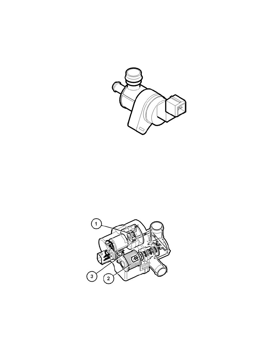
The leak diagnostic unit consists of a plastic housing with:
1. electrical air pump
2. a valve/solenoid which governs the air flow in the unit
3. a heater element (PTC resistor) which warms up the pump.
The electrical pump, valve and heater element in the unit are supplied with voltage by the system relay. The pump, valve and heater element are
grounded (control) in the engine control module (ECM).
When leak diagnostics are not active, the valve is held open to ambient air for EVAP control to be carried out.
During leak diagnostics the pump in the leak diagnostic unit starts. The valve in the unit is operated by the engine control module (ECM) by grounding