XC90 AWD V8-4.4L VIN 85 B8444S (2005)

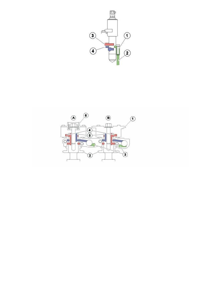
1: Oil filter reset valve camshaft.
2: Oil duct (pressure, inlet).
3: Duct leading to CVVT unit chamber (deployment).
4: Duct leading to CVVT unit chamber (deployment).
The camshaft reset valve controls the oil flow to the continuous variable valve timing (CVVT) unit. The engine control module (ECM) uses a pulse
width modulation (PWM) signal to control the valve. See also:
Controlling, CVVT units
The CVVT units are the "Vane" type which means that the CVVT unit rotors are turned by oil pressure on one, or the other, side of the rotor wings.
A: CVVT unit exhaust
B: CVVT unit inlet
1: Timing belt pulley inlet camshaft (primary, inlet camshaft driven by the crankshaft).
2: Timing belt pulley inlet -/exhaust camshaft (secondary, exhaust camshaft driven by inlet camshaft).
3: Oil duct reset valve camshaft (pressure).
4: Oil duct for controlling CVVT unit.
5: Oil duct for return CVVT unit.
6: Spring (CVVT unit exhaust camshaft only).
The continuous variable valve timing (CVVT) unit allows the position of the camshaft to be adjusted relative to the crankshaft.
The camshaft is secured to the CVVT unit rotor. The rotor (and with it the camshaft) rotates in relation to the timing belt pulley (1) by the oil pressure
building up on one or both sides of the rotor vanes in the CVVT unit.
The difference in function between the exhaust camshaft (A) and inlet camshaft (B) CVVT unit is that the exhaust camshaft CVVT unit is equipped with
a spring. The force of the spring makes the CVVT unit deploy the camshaft. The function causes faster deployment of the exhaust camshaft at engine
start-up, before the oil pressure build in the engine.
Control occurs according to the following during deployment/return of the camshaft.
