
XC90 AWD V8-4.4L VIN 85 B8444S (2005)
If there is air leakage for example, the short-term fuel trim will quickly be offset to a new position (B) and will then work for example between 1.10
(+10%) and 1.20 (+20%), although still at an amplitude of 5%, but with an offset in relation to the original center line (A). The injection period has then
been increased to compensate the increase in the amount of air.
The adaptive functions will correct the change, so that the short-term fuel trim will work around the new center line (B) where it will again have its full
range of control available.
Put simply, fuel trim is a measurement of the difference (C) between the original short-term fuel trim center line (A) and the new center line (B).
The adaptive functions are split into various operational ranges based on the load and speed of the engine.
The different adaptation ranges can be read off.
The adaptive adjustments of injection time are continuously stored in the engine control module (ECM). This means that, at different operating ratios,
the correct mixture ratio is achieved before the heated oxygen sensor (HO2S) reaches operating temperature.
The diagnostic trouble code (DTC) is stored in the engine control module (ECM) if any adaptation value is too high or too low.
Fuel pressure regulation
General
Fuel pressure regulation for demand controlled fuel pumps (DECOS - DEmand COntrolled fuel Supply) means that the fuel pressure is controlled
steplessly by varying the output of the fuel pump. The design of the system allows a greater maximum pressure (approximately 650kPa) in the fuel pump.
This pressure is used in extreme situations, such as heavy engine load for example
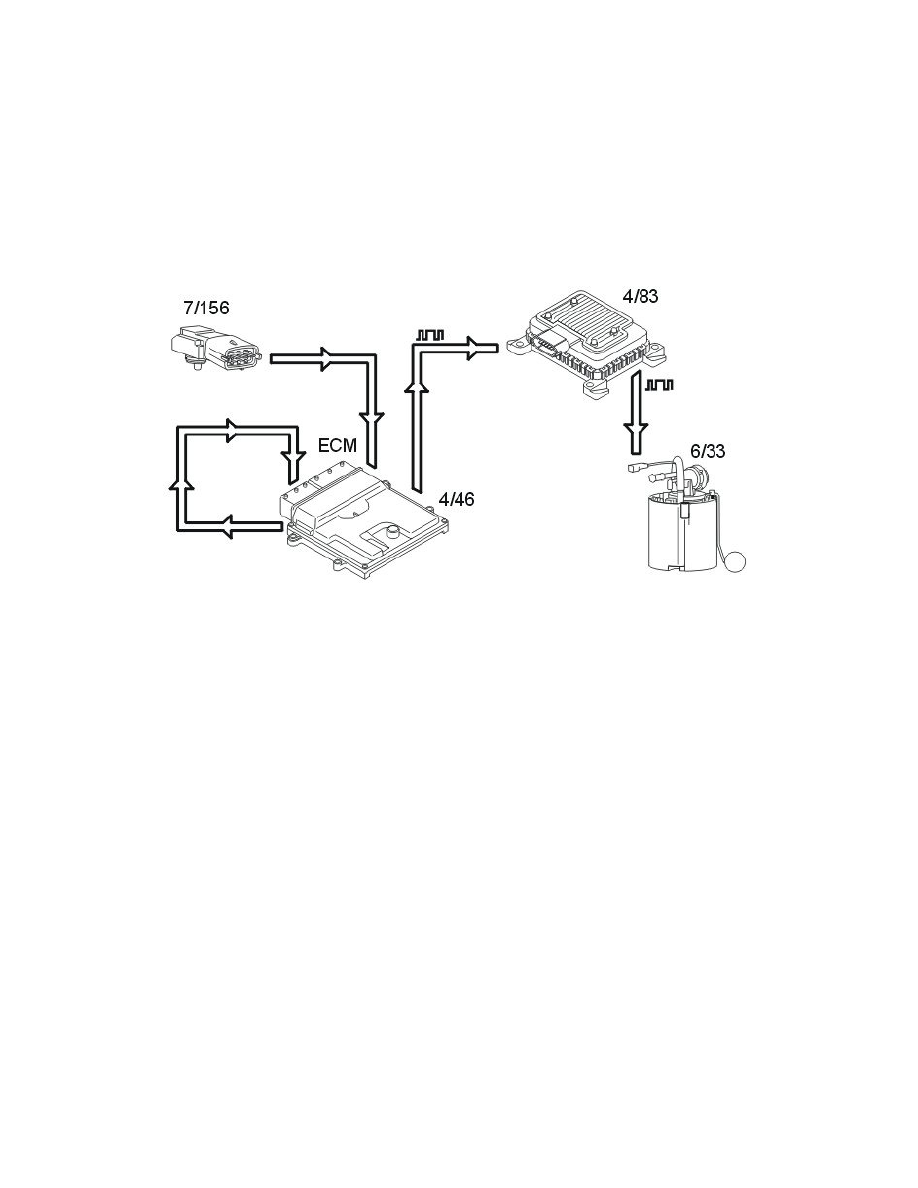
The following components are used for fuel pressure regulation:
-
engine control module (ECM) (4/46) with integrated atmospheric pressure sensor
-
fuel pump control module (4/83)
-
fuel pressure sensor with fuel temperature sensor (7/156)
-
fuel pump with by-pass valve (6/33).
The time taken for the engine start procedure can be reduced by rapidly increasing the pressure in the fuel rail when the engine control module (ECM)
receives a signal about the position of the ignition switch from the central electronic module (CEM).
The engine control module (ECM) is better able to calculate the injection period using the signal from the atmospheric pressure sensor and fuel pressure
sensor. This particularly improves the cold starting characteristics of the engine.
The advantages of varying the output of the fuel pump so that it is not always at full power are:
-
the total power consumption of the fuel pump (FP) is reduced, reducing the load on the power supply system
-
the service life of the fuel pump (FP) is increased
-
fuel pump noise is reduced.
Control
The engine control module (ECM) calculates the desired fuel pressure. A signal is then transmitted to the fuel pump control module indicating the
desired fuel pressure. Serial communication between the engine control module (ECM) and the fuel pump control module is used to carry the signal. The
fuel pump control module then operates the fuel pump unit to obtain the desired pressure using a pulse width modulation voltage on the ground lead. The
fuel pump (FP) can be controlled steplessly by changing the pulse width modulation (PWM) signal. Only that pressure which is required at that specific
time will then be released to the fuel rail/injectors. The value of the pulse width modulation (PWM) signal is a measurement of the operational load of
the fuel pump (FP) (% duty, 100% = maximum pressure).
The engine control module (ECM) continuously monitors the fuel pressure using the signal from the fuel pressure sensor. This allows the desired fuel
pressure to be reached, and if necessary a signal is transmitted to the fuel pump control module requesting that the fuel pressure is adjusted.
The engine control module (ECM) attempts too obtain a constant fuel pressure (approximately 380kPa relative to atmospheric pressure with the engine