
XC90 FWD L6-3.2L VIN 98 B6324S (2007)
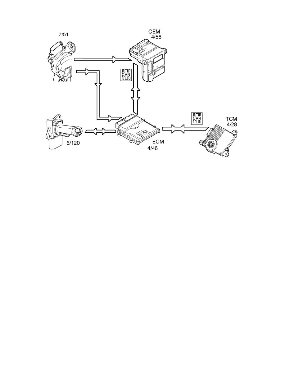
To ensure that the correct throttle angle is reached, the engine control module (ECM) (4/46) controls the throttle shutter in the throttle unit (6/120),
mainly using the signal from:
-
Accelerator pedal (AP) position sensor (7/51)
-
the throttle position (TP) sensor on the electronic throttle unit.
Additional signals and parameters are used to ensure optimum throttle control. By example by compensating for:
-
the load from the air conditioning (A/C) compressor
-
the load from the transmission depending on the selected gear mode
-
engine coolant temperature (ECT)
-
mass air flow through the intake manifold
-
manifold absolute pressure (MAP) in the intake manifold.
The position of the throttle is measured by two potentiometers, in the throttle position (TP) sensor, which are on the throttle unit. These are connected, so
that potentiometer 1 produces a higher voltage as the throttle angle increases, while potentiometer 2 does the opposite.
In a combustion engine, the difference between the minimum and maximum airflow is considerable. The smaller air flows need more thorough
regulation, so the potentiometer signal from potentiometer 1 is amplified approximately 4 times in the engine control module (ECM) before it reaches the
AC/DC converter in the engine control module (ECM). This means that there are three, two real and one fictitious, input signals available to the engine
control module (ECM). These signals are used to determine the position of the throttle and to deploy the damper motor to the correct position. In general
the amplified signal is primarily used for small throttle angles (small air flows), which are desirable when a high degree of accuracy is required, for idle
air trim for example.
Because the signal is amplified, it reaches its maximum value as early as approximately a quarter of maximum deployment.
The engine control module (ECM) primarily uses the signal from potentiometer 1 as a measurement of throttle opening. The signal from potentiometer 2
is mainly to check that potentiometer 1 is working. The engine control module (ECM) then uses the signal to calculate a throttle angle (actual value).
This is the actual throttle angle. The value for the actual throttle angle is used by those functions in the engine control module (ECM) which depend on
this information so that the throttle can be correctly regulated.
There is an adaptation (learning) in the engine control module (ECM) so that the control module can calculate how the damper motor needs to be
controlled. See "Adaptation of the throttle unit" below.
The throttle angle is regulated so that the actual angle (actual value) is the same as the angle calculated by the engine control module (ECM) (desired
value). The engine control module (ECM) also uses the values that were stored during adaptation of the throttle angle, and the actual signals from the
potentiometers.
The damper motor is deployed by the integrated power stage in the engine control module (ECM) using a pulse width modulation (PWM) signal. The
torsion from the opening and return springs in the electronic throttle unit is also used. If there is a fault in the engine control module (ECM) so that the
throttle unit cannot be operated or powered, the springs in the throttle unit will turn the throttle disc to the limp home position (return position). This
return position gives a throttle angle large enough to allow the car to be driven to a workshop, although with considerably reduced driveablity.
Throttle angle