
GV CABRIO L4-1300cc 1.3L SOHC VIN 5 2-bbl (1990)
Engine Control Module: Testing and Inspection
Control Unit Voltage Supply Inspection
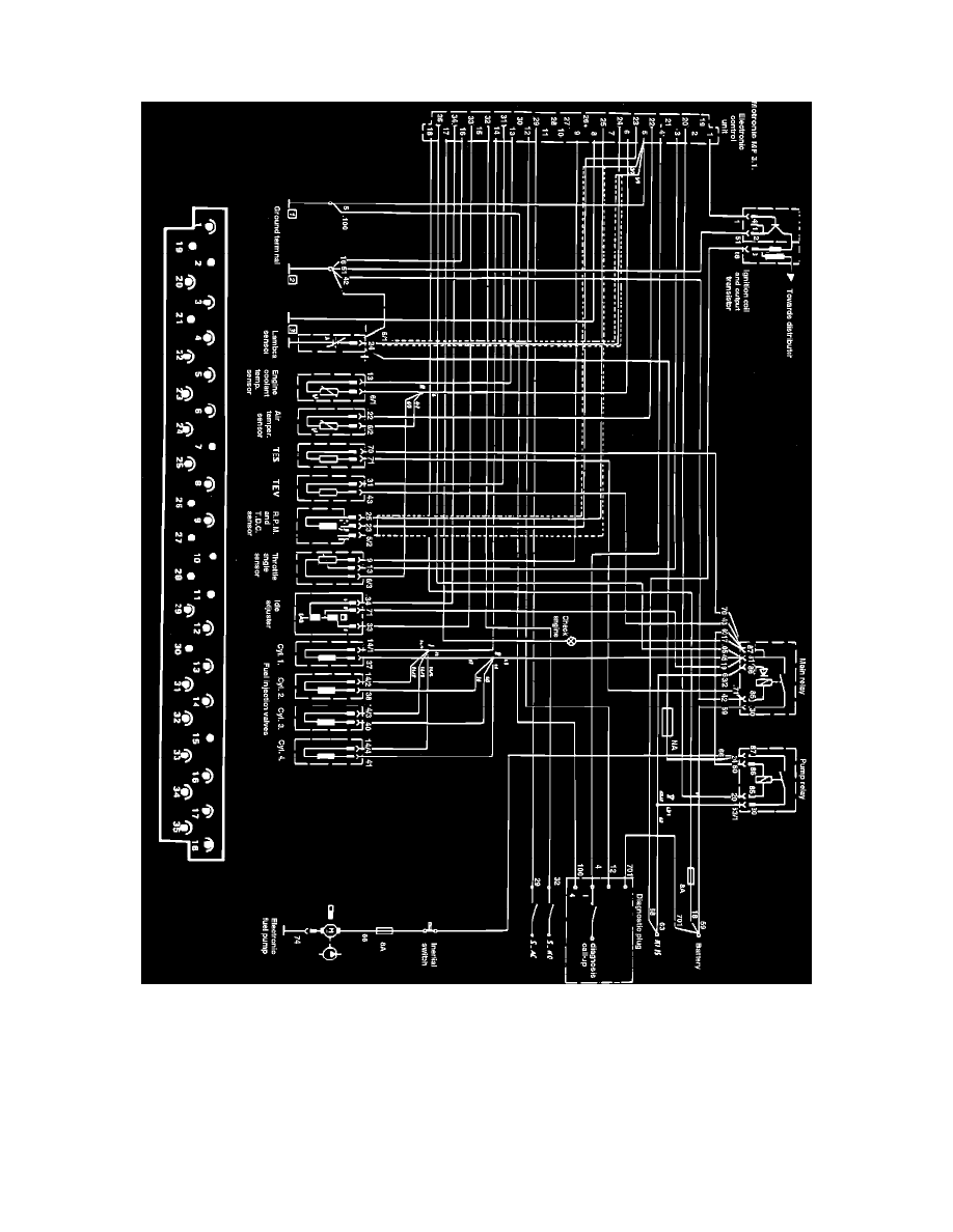
Fig. 3 Bosch Motronic Electronic Engine Control System Terminal Identification
Perform the following test procedure using a suitable digital volt/ohmmeter, referring to Fig 3 for terminal identification.
1.
Locate ECU behind passenger side of instrument panel, then disconnect 35 pin connector from ECU.
2.
With ignition switch in Run position, probe ECU terminal 35 with voltmeter positive lead and ECU terminal 5 with negative lead. If battery
voltage is not present, turn ignition switch Off and proceed as follows:
a. Inspect fuse near main relay.
b. Check resistance between ECU terminal 5 and battery negative terminal, resistance should be approximately 0 ohms but no greater than 1
ohm. If infinite resistance is indicated check for an open. If high resistance is indicated, check continuity between ECU terminal 35 and main
relay terminal 87.