
GVL L4-1116cc 1.1L SOHC VIN 2 2-bbl (1988)
PREP:
Remove 10 mm nut holding unit to evaporator case. Radio chassis &/or right side console trim panel may be removed for additional
access. Then pull unit and harness out to left aide of console.
NOTE:
Turn ignition switch > OFF before disconnecting or reconnecting unit to avoid damage to electronic components.
TROUBLESHOOTING PROCEDURE
STEP
1:
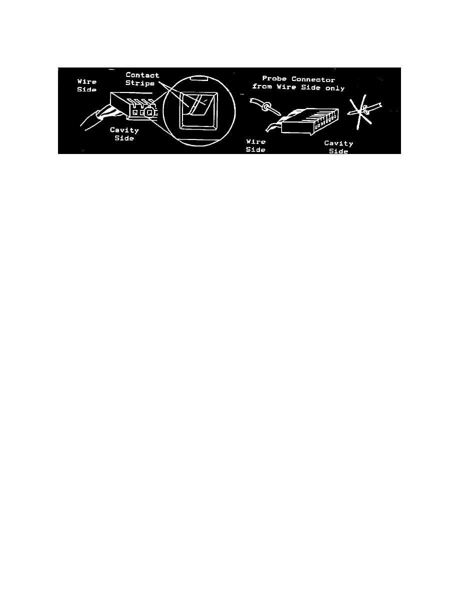
Lift locktab an unit and disconnect unit from harness.
Inspect each cavity in connector; be sure terminals are
secure and contact strips are visible as shown below to
make positive contact with pins of control unit. Probe
connector only from wire side, not cavity side, to avoid damage to terminal contact strips.
2:
Ignition switch > ON, temp control > MAX COOL.
Check for 12v @ connector position 6. (Also check for 6-12v at connector position 9 on early type system) If voltage present, go to Step 3. If
no voltage at 6, check wiring & fuses. (If no voltage at position 9, check red wire to power source at splice)
TROUBLESHOOTING PROCEDURE
STEP
3:
Evaporator blower switch > HI.
Check for ground at connector positions 5 & 8. If ground present, go to Step 4. If no ground at 5, check wire to blower slide switch. If
no ground at 8, check wire to relay mounting bracket.
4:
Ignition switch > OFF, reconnect unit to harness.
Connect jumper wire between positions 1 & 4. Ignition switch > ON, blower switch > ON. If clutch engages, go to step 5. If no
engagement, go to step 8.
5:
Ignition switch > OFF, disconnect unit from harness.
Dash temperature control > MAX COOL. Check resistance between connector positions 3 & 4 is less than 200 ohms. If OK, go to Step
6. If over 200 ohms or infinite (open), check wiring and connections in loop; if OK, replace control switch.
6:
Ignition switch still > OFF, unit disconnected.
Check resistance between connector positions 1 & 2 is:
9950 @ 50~F
4650 @ 80~F
7650 @ 60~F
3650 @ 90~F
5950 @ 70~F
2950 @ 100~F
If OK, go to Step 7. If over 10% variance, check connector in thermistor wire loop & recheck resistance at thermistor pigtail.
7.
Ignition switch still > OFF, unit disconnected. Check resistance between ground and each of connector positions 1, 2, 3, & 4 in infinite. If
OK, go to Step 8. If continuity present, check all related wiring to find source of short.
8.
Ignition switch still > OFF, unit disconnected. Connect jumper wire between connector positions 6 & 7. Ignition switch > ON. Check if
compressor clutch engages. If clutch engages, replace electronic control unit. If no engagement, check wiring & connections to clutch.
NOTES:
* Early and late style Thermostat Control Boxes are not interchangeable.
*
When connecting the early style (blue case, 9-pin) box be sure that you are connecting pine 1 thru 9, not pins 2 thru 10; the two
gray wires for the thermistor probe should be at the left end (pins 1 & 2).