
Yugo L4-1300cc 1.3L (1991)
Ignition Control Module: Testing and Inspection
Output Transistor Test
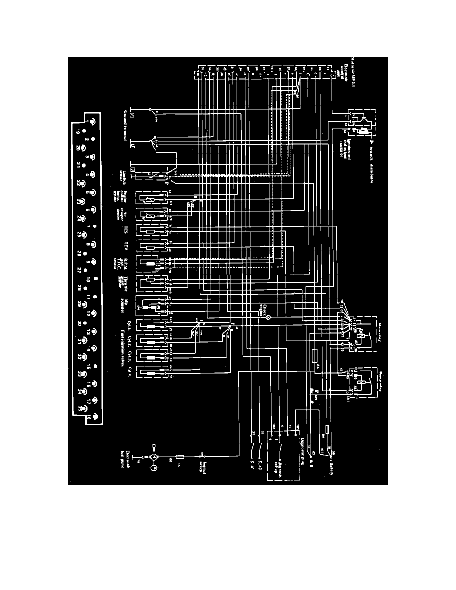
Refer to Fig. 5 when performing the following procedure.
Fig. 5 Bosch Motronic Electronic Engine Control System Terminal Identification
1.
Using a suitable digital ohmmeter, check resistances are as follows:
a. Probe output transistor terminal 4 with positive lead of ohmmeter and terminal 2 with negative lead of ohmmeter. Resistance should be
690-790 ohms. Reverse ohmmeter connections, resistance should be 720-820 ohms.
b. With output transistor blue wire disconnected from ignition coil negative terminal, probe transistor terminal 4 with positive lead of ohmmeter
and the end of the blue wire with negative lead of ohmmeter. Resistance should be 670-770 ohms. Reverse ohmmeter connections, resistance
should be infinite.
c. With output transistor blue wire disconnected from ignition coil negative terminal, probe transistor terminal 2 with negative lead of ohmmeter