
Alignment: Technical Service Bulletins (page 4 of 5)
- Make
- Acura (Honda)
- Model
- CL 3.2CL
- Engine
- V6-3.2L SOHC
- Year
- 2003
- Section
- Alignment
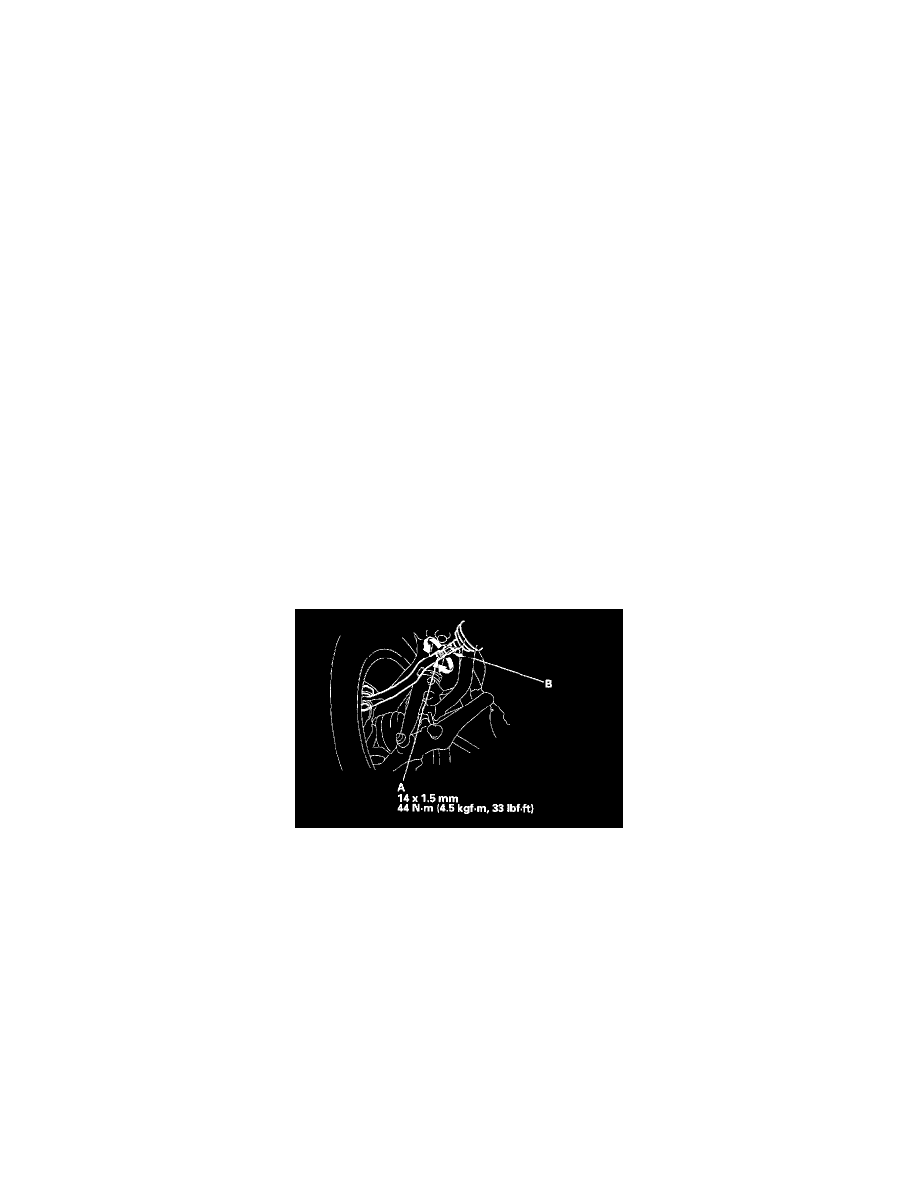
2. Remove the self-locking nut (A) on the end of the radius rod (B).
3. Remove the flange bolts at the radius rod (B) on the lower arm, and remove the radius rod.
4. Adjust the caster angle by increasing/decreasing the adjusting shims (C).
Note these items during adjustment:
^
Do not use more than two adjusting shims.
^
One adjusting shim changes the caster angle by 35° and the caster angle can be adjusted by 1°10' maximum.
^
One adjusting shim is 3.2 mm (0.13 inch) in thickness.
5. After the adjustment, install the radius rod onto the lower arm, and tighten the flange bolts.
6. Tighten the new self-locking nut to the specified torque.
Camber Inspection
Use commercially available computerized four wheel alignment equipment to measure wheel alignment (caster, camber, toe, and/or turning angle).
Follow the equipment manufacturer's instructions.
1. Check the camber angle.
Camber angle:
Front: 0°00' ± 1°
Rear: - 0°30' ± 1°
2. If out of specification, check for bent or damaged suspension components.
Front Toe Inspection/Adjustment
Use commercially available computerized four wheel alignment equipment to measure wheel alignment (caster, camber, toe, and/or turning angle).
Follow the equipment manufacturer's instructions.
1. Check the tire pressure.
2. Center the steering wheel spokes.
3. Check the toe with the wheels pointed straight ahead.
Front Toe-in: 0 ± 2 mm (0 ± 1/16 inch)
^
If adjustment is required, go on to step 4.
^
If no adjustment is required, remove the alignment equipment.
4. Loosen the tie-rod locknuts (A), and turn the tie-rods until the measurements are the same for the left and right wheels.
5. After adjusting, tighten the tie-rod locknuts. Reposition the tie-rod boot if it is twisted or displaced.
Rear Toe Inspection/Adjustment
Use commercially available computerized four wheel alignment equipment to measure wheel alignment (caster, camber, toe, and/or turning angle).
Follow the equipment manufacturer's instructions.
1. Release the parking brake to avoid an incorrect measurement.
2. Check the toe.
Rear Toe-in: 2 ± 2 mm (1/16 ± 1/16 inch)
^
If adjustment is required, go to step 3.
^
If no adjustment is required, remove the alignment equipment.
Pinch or Ctrl + scroll to zoom. Double-tap to reset.
Parts & tools for this job For 2003 Acura CL 3.2L
- TOOLTie rod end toolSearch: tie rod end puller
- TOOLBall joint separatorSearch: ball joint separator
- FLUIDPower steering fluidSearch: Acura power steering fluid
Links open Amazon search results in a new tab. As an Amazon Associate I earn from qualifying purchases.