
3.2TL TYPE S V6-3.2L SOHC (2002)
Yaw Rate Sensor: Description and Operation
Yaw Rate Sensor
The yaw rate sensor detects the direction change (angular speed) of the vehicle. The sensor is an oscillation gyro.
Sensor Element Structure
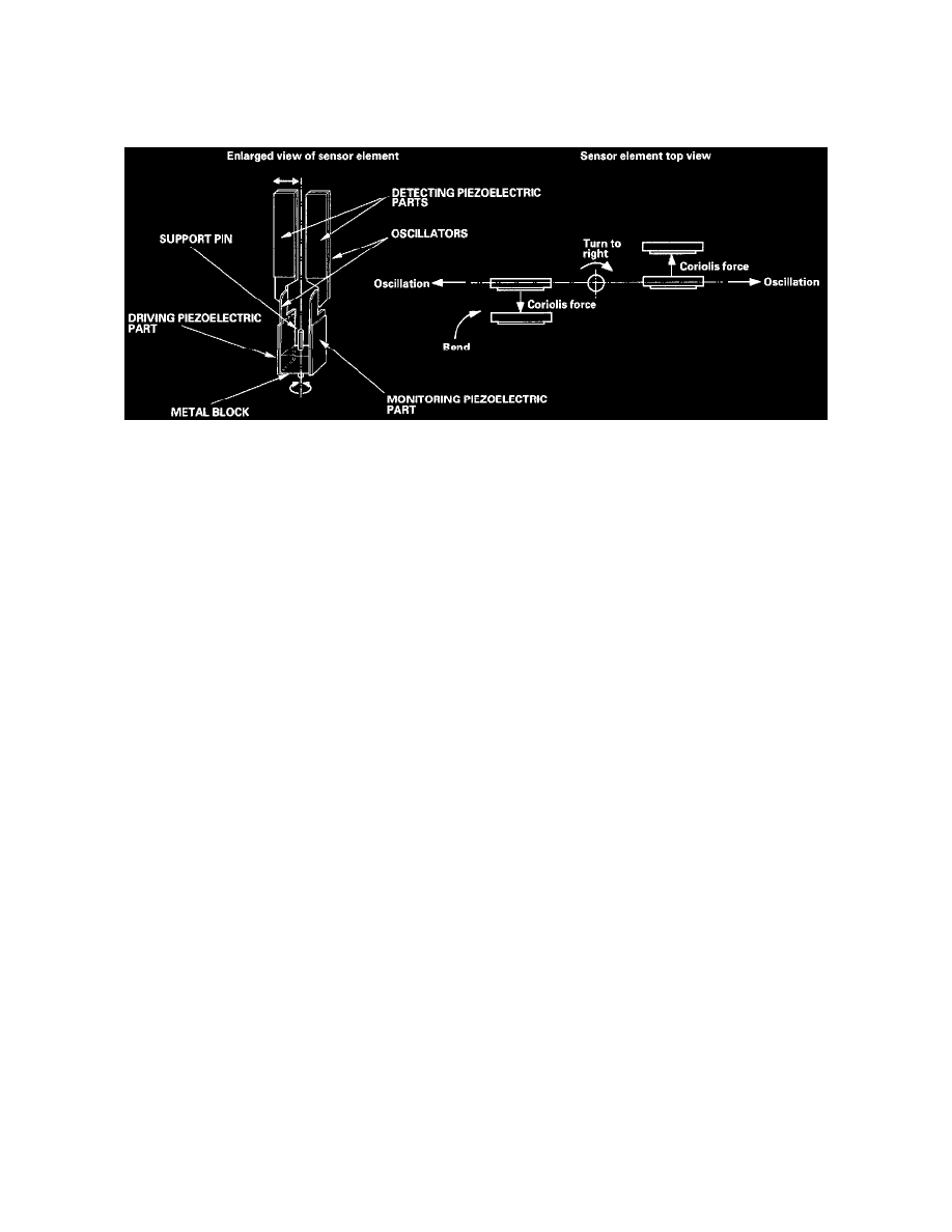
The sensor element is shaped like a tuning fork, and it consists of the piezoelectric parts, the metal block, and the support pin. There are four
piezoelectric parts: one to drive the oscillators, one for monitoring that maintains the oscillation at a regular frequency, and two to detect angular
velocity. The two oscillators have a 90 degree twist in the center, are connected at the bottom by the metal block, and supported by the support pin. A
detecting piezoelectric part is attached to the top of each oscillator. The driving piezoelectric part is attached to the bottom of one oscillator, and the
monitoring piezoelectric part is attached to the bottom of the other oscillator.
Oscillation Gyro Principles
The piezoelectric parts have "electric/mechanical transfer characteristics." The piezoelectric parts bend vertically when voltage is applied to both sides
of the parts, and voltage is generated between both sides of the piezoelectoric parts when then are bent by an external force. The oscillation gyro
factions by utilizing this characteristic of the piezoelectric parts and "Coriolis force." (Coriolis force deflects moving objects as a result of the earth's
rotation.) In the oscillation gyro, this force moves the sensor element when the angular velocity is applied.
Operation
1. The driving piezoelectric part oscillates the oscillator by repeatedly bending and returning when an AC voltage at 6 kHz is applied to the part, The
monitoring-side oscillator resonates because it is connected to the driving-side oscillator by the metal block.
2. The monitoring piezoelectric parts bend in proportion to the oscillation and outputs voltage (the monitor signal). The VSA control unit control
circuit controls the drive signal to stabilize the monitor signal.
3. When the vehicle is stopped, the detecting piezoelectric parts oscillate right and left with the oscillators, but no signal is output because the parts
are not bent (no angular force).
4. When the vehicle turns to the right, the sensor element moves in a circular motion with the right oscillator bending forward and the left oscillator
bending rearward. The amount of forward/rearward bend varies according to the angular velocity of the vehicle.
5. The detecting piezoelectric parts output voltage (the yaw rate signal) according to the amount of bend. The amount of vehicle direction change is
determined by measuring this voltage.