
CL TYPE S V6-3.2L SOHC (2001)
Emitting Diode (LED), and a light receiving part (photo transistor). As the disk rotates, it interrupts the light from the LED. The light which passes
through a slit is converted into electric current by the photo transistor, and the waveform of this electric current is converted by the comparator into a
square wave output of the disk's rotation.
The analysis performance of the system is improved by providing the fixed slit in front of the LED, and thereby identifying the brightness and
darkness of the light which is received at the photo transistor.
The output signal is a 2-phase output (A-phase and B-phase), and the steering wheel turning angle and the turning direction are calculated by the VSA
control unit.
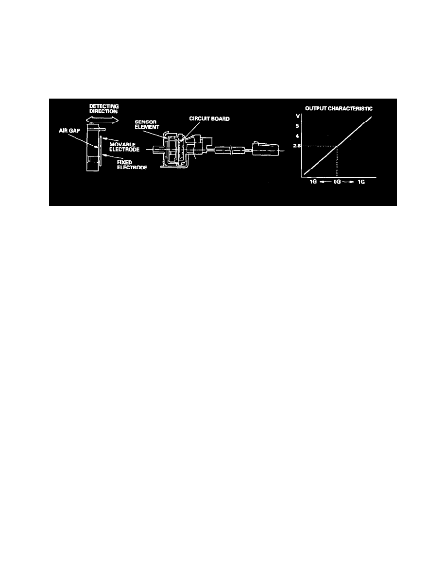
Lateral Acceleration Sensor
The lateral acceleration sensor detects crisscross direction acceleration against the fixed electrode and movable electrode. The sensor is a static
electricity capacity type, and the sensor detects static electricity between the fixed electrode and the movable electrode which is changed by lateral
acceleration.
Yaw Rate Sensor
The yaw rate sensor detects the direction change (angular speed) of the vehicle. The sensor is an oscillation gyro.
Sensor Element Structure
The sensor element is shaped like a tuning fork, and it consists of piezoelectric parts, a metal block, and a support pin.
There are four piezoelectric parts: one to drive the oscillators, one for monitoring that maintains the oscillation at a regular frequency, and two to
detect angular velocity. The two oscillators have a 90 degree twist in the center, are connected at the bottom by the metal block, and supported by the
support pin. A detecting piezoelectric part is attached to the top of each oscillator. The driving piezoelectric part is attached to the bottom of one
oscillator, and the monitoring piezoelectric part is attached to the bottom of the other oscillator.
Oscillation Gyro Principles
The piezoelectric parts have "electro/mechanical transfer characteristics." The piezoelectric parts bend vertically when voltage is applied to both sides
of the parts, and voltage is generated between both sides of the piezoelectric parts when then are bent by an external force. The oscillation gyro
functions by utilizing this characteristic of the piezoelectric parts and "Coriolis force." (Coriolis force deflects moving objects as a result of the earth's
rotation.) In the oscillation gyro, this force moves the sensor element when the angular velocity is applied.
Operation
1. The driving piezoelectric part oscillates the oscillator by repeatedly bending and returning when an AC voltage at 6 kHz is applied to the part, The
monitoring-side oscillator resonates because it is connected to the driving-side oscillator by the metal block.
2. The monitoring piezoelectric parts bends in proportion to the oscillation and outputs voltage (the monitor signal). The VSA control unit control
circuit controls the drive signal to stabilize the monitor signal.
3. When the vehicle is stopped, the detecting piezoelectric parts oscillate right and left with the oscillators, but no signal is output because the parts
are not bent (no angular force).
4. When the vehicle turns to the right, the sensor element moves in a circular motion with the right oscillator bending forward and the left oscillator
bending rearward. The amount of forward/rearward bend varies according to the angular velocity of the vehicle.