
CL TYPE S V6-3.2L SOHC (2001)
Fuel Gauge: Testing and Inspection
Fuel Gauge Test
NOTE: For the fuel gauge system circuit diagram, refer to the Gauges Circuit Diagram.
1. Check the No.9 BACK UP LIGHT INSTRUMENT LIGHT (7.5 A) fuse in the driver's under-dash fusel relay box before testing.
2. Remove the spare tire lid.
3. Remove the access panel from the floor.
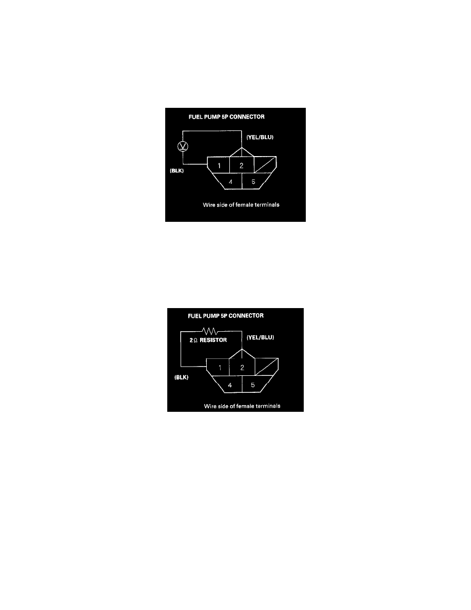
4. Turn the ignition switch OFF, then disconnect the fuel pump 5P connector.
5. Measure voltage between the fuel pump 5P connector terminals No.1 and No.2 with the ignition switch ON (II). There should be between 5 and 8
V.
-
If the voltage is as specified, go to step 6.
-
If the voltage is not as specified, check for:
-
an open in the YEL/BLU or BLK wire.
-
poor ground (G552).
6. Turn the ignition switch OFF.
7. Install a 2 Ohms resistor between the fuel pump 5P connector terminals No.1 and No.2, then turn the ignition switch ON (II).
8. Check that the pointer of the fuel gauge starts moving toward the "F" mark.
-
If the pointer of the fuel gauge does not move at all, replace the gauge.
-
If the gauge is OK, inspect the fuel gauge sending unit.
NOTE:
-
Turn the ignition switch OFF before the pointer reaches "F" on the gauge dial. Failure to do so may damage the fuel gauge.
-
The fuel gauge is a bobbin (cross-coil) type, hence the fuel level is continuously indicated even when the ignition switch is OFF, and the
pointer moves more slowly than that of a bimetal type.