
Integra L4-1590cc 1.6L DOHC FI (1987)
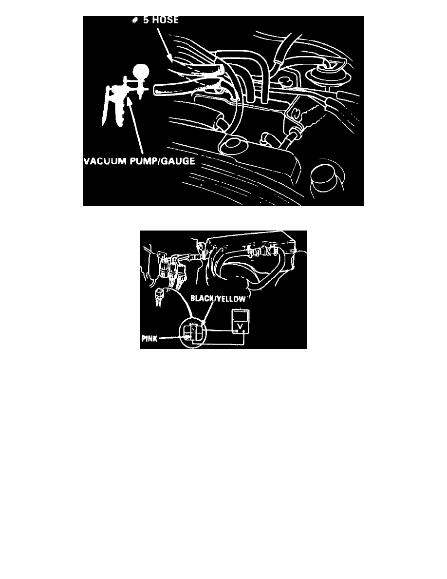
Fig. 2 No. 5 Vacuum Hose Location
Fig. 3 6 Pin Connector Terminal Identification
SOLENOID VALVE
1.
Start engine and allow to reach normal operating temperature (cooling fan cycling).
2.
Disconnect No. 5 vacuum hose from intake manifold, Fig. 2, and check for vacuum using suitable vacuum gauge. If no vacuum is present, check
for defective vacuum port. If vacuum is present, check hose for blockage, cracks or improper connection. If hose is OK, reconnect it to manifold.
3.
Disconnect 6 pin connector in engine compartment, then connect voltmeter positive lead to black/yellow terminal and negative lead to pink
terminal, Fig. 3.
4.
Start engine and check for voltage within 20 seconds after restart. If voltage is evident, replace solenoid valve and retest. If no voltage is present,
proceed to next step.
5.
Connect positive lead of voltmeter to black/yellow terminal of connector and negative lead to body ground, then check for voltage within 20
seconds after restart. If no voltage is present, repair open in black/yellow wire between solenoid valve and No. 11 fuse. If voltage is present, check
for open in pink wire between solenoid valve and ECU, and repair as necessary. If wire is OK, check ECU for proper operation.
6.
Restart engine and allow to reach normal operating temperature.
7.
Disconnect 6 pin connector in engine compartment, then connect voltmeter positive lead to black/yellow wire terminal and negative lead to Pink
wire terminal.
8.
Check for voltage with engine idling and within 30 seconds after engine restart.
9.
If no voltage is evident, replace solenoid valve and retest. If voltage is present, check for short in pink wire between solenoid valve and ECU, and
repair as necessary. If wire is OK, check ECU for proper operation.