
Integra LS Coupe L4-1834cc 1.8L DOHC MFI (1997)
Maintenance Required Lamp/Indicator: Description and Operation
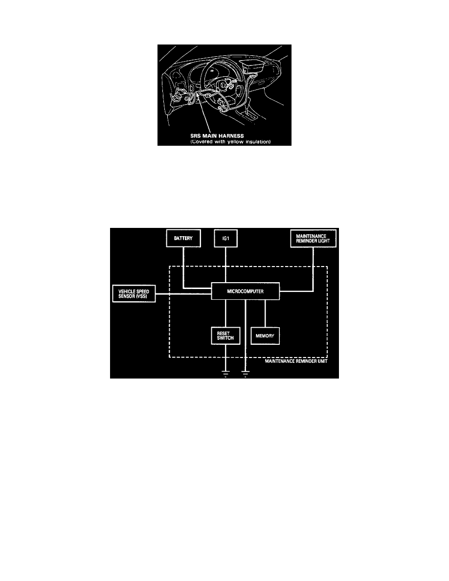
MAINTENANCE REMINDER SYSTEM
CAUTION:
All SRS wire harnesses are covered with yellow insulation. Before you disconnect any part of an SRS wire harness, disconnect the airbag connectors.
Whenever the ignition switch is ON, or has been turned OFF for less than three minutes, be careful not to bump the SRS unit; the airbags could
accidentally deploy and cause damage or injuries.
For additional precautions, refer to the SRS section See: Restraint Systems/Service Precautions.
Based on signals received from the vehicle speed sensor (VSS), the microcomputer in the maintenance reminder unit, which is located behind the
dashboard lower cover, computes the distances traveled. When you turn the ignition switch ON (II), the reminder light in the gauge assembly will come
on for 2 seconds (bulb check function). At 9,650 ± 160 km (6,000 ± 100 miles) intervals, the reminder light will glow for 2 seconds and then blink 10
seconds after you turn the ignition switch ON (II). This will repeat every time you turn the ignition switch ON (II) until the car reaches 12,070 ± 160 km
(7,500 ± 100 miles).
Beyond the 12,070 ± 160 km (7,500 ± 100 mile) interval, the light will continue to glow after the bulb check until you turn the ignition switch OFF or
reset the unit.
To reset the unit, the car must be parked and the ignition switch must be ON (II). Press the reset button ON the unit for more than 3 seconds, and the
reminder light will go OFF.
NOTE:
Turn the ignition switch OFF before you remove the 5-P connector from the maintenance reminder unit, otherwise you will cancel all data in the
memory.
The data will remain in the memory even when the ignition switch is turned OFF, or if the unit is disconnected. When the ignition switch is turned ON
(II), and the car is driven, additional data will be stored.