
Integra RS Coupe L4-1834cc 1.8L DOHC MFI (1998)
Shift Control Solenoid Valve: Testing and Inspection
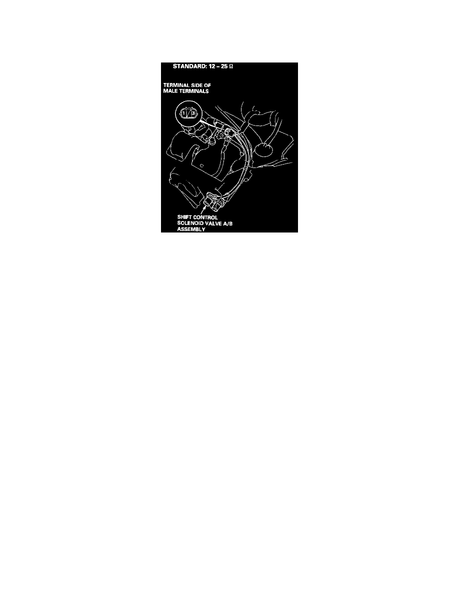
NOTE: Shift control solenoid valves A and B must be removed/replaced as an assembly.
1. Disconnect 3P connector from the shift control solenoid valve A/B assembly.
2. Measure the resistance between the No. 1 terminal (solenoid valve A) of the shift control solenoid valve connector and body ground and between
the No. 3 terminal (solenoid valve B) and body ground.
3. Replace the shift control solenoid valve assembly if the resistance is out of specification.
4. If the resistance is within the standard, connect the No. 1 terminal of the shift control solenoid valve connector to the battery positive terminal. A
clicking sound should be heard. Connect the No. 3 terminal to the battery positive terminal. A clicking sound should be heard. Replace the shift
control solenoid valve assembly if no clicking sound is heard.