
Legend Coupe V6-3206cc 3.2L SOHC FI (1991)
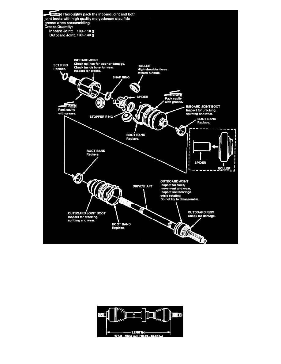
Fig. 2 Exploded View Of Driveshaft Assembly
1.
Disassemble driveshaft assembly referring to, Figs. 1 and 2. Mark rollers and roller grooves for assembly reference.
2.
Assemble driveshaft assembly in the reverse order of disassembly, noting the following:
a. Pack bearings, joint boot cavity and both CV joints with suitable grease prior to installation.
b. Install rollers and bearing races on spider shafts, then position spider assembly into inboard CV joint. On Legend models, position rollers on
spider with their high shoulders facing outward.
c. Avoid getting grease or oil on rubber components.
d. On Integra models, position new boot bands on small ends of boots so they are centered between protrusions at each end of driveshaft, then
expand and contract boots until they return to normal shape and length.
Fig. 3 Driveshaft Length Adjustment