
RDX L4-2.3L Turbo (2008)
Information Bus: Initial Inspection and Diagnostic Overview
General Troubleshooting Information
Troubleshooting CAN Circuit Related Problems
NOTE: Check the PCM for DTCs and troubleshoot PCM or F-CAN loss of communication errors first.
Using the HDS (Preferred Method)
1. Go to B-CAN System Diagnosis Test Mode A See: Diagnostic Trouble Code Tests and Associated Procedures/B-CAN System Diagnosis Test
Mode A to check for "Connected units" and DTCs.
2. If no DTCs are retrieved, go to B-CAN System Diagnosis Test Mode C See: Diagnostic Trouble Code Tests and Associated Procedures/B-CAN
System Diagnosis Test Mode C or D.
Without HDS (Use only if the HDS is unavailable)
1. Check for communication circuit problems using B-CAN System Diagnostic Test.
2. Check for DTCs.
3. Sort, and then troubleshoot the DTCs in this order.
-
Battery voltage DTCs
-
Internal error DTCs
-
Loss of communication DTCs (beginning with the lowest number first; for example, if B1008 and B1011 are retrieved, troubleshoot B1008
first)
-
Signal error DTCs
4. If no DTCs are retrieved, use B-CAN System Diagnostic Test Mode 2 to check all inputs related to failure.
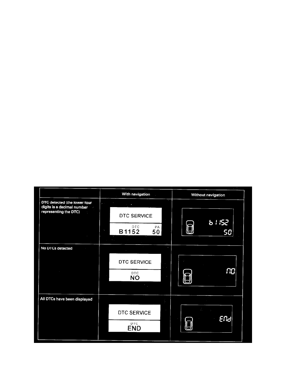
How to display DTCs on the gauge control module
Set the B-CAN System Diagnosis Test Mode 1. While in Test Mode 1, the DTCs which have been detected and stored individually by various B-CAN
(Body-controller Area Network) units, will be shown one by one on the LCD display when the communication between the MICU and the gauge control
module is normal. To scroll through the DTCs, press the select/reset button.
The unit that has stored the code can be identified by the number shown on the multi-information display.