
RL V6-3.5L (2007)
Is there more than 0.2 V?
YES - Repair open in the wire(s) that had more than 0.2 V between G101 and the PCM (A1, A2, A3, and B15).
NO - Go to step 51.
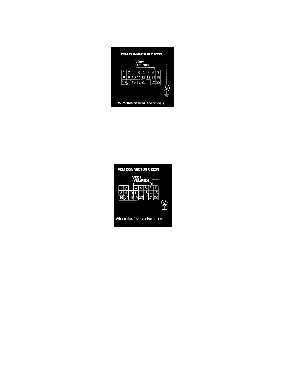
51. Measure voltage between body ground and PCM connector terminal C6.
Is there about 5 V?
YES - Go to step 59.
NO - Go to step 52.
52. Turn the ignition switch OFF.
53. Disconnect the connector from each of the following sensors, one at a time, and measure voltage between body ground and PCM connector
terminal C6 with the ignition switch ON (II).
-
Manifold absolute pressure (MAP) sensor
-
Output shaft (countershaft) speed sensor
Is there about 5 V?
YES - Replace the sensor that restored 5 V when disconnected.
NO - Go to step 54.
54. Turn the ignition switch OFF.
55. Jump the SCS line with the HDS.
56. Disconnect the connectors from these sensors:
-
Manifold absolute pressure (MAP) sensor
-
Output shaft (countershaft) speed sensor
57. Disconnect PCM connector C (22P).