
RL V6-3.5L (2007)
Engine Control Module: Testing and Inspection
How to Troubleshoot Circuits At the PCM Connectors
How to Troubleshoot Circuits at the PCM Connectors
Special Tools Required
-
Digital multimeter or a commercially available digital multimeter
-
Backprobe set
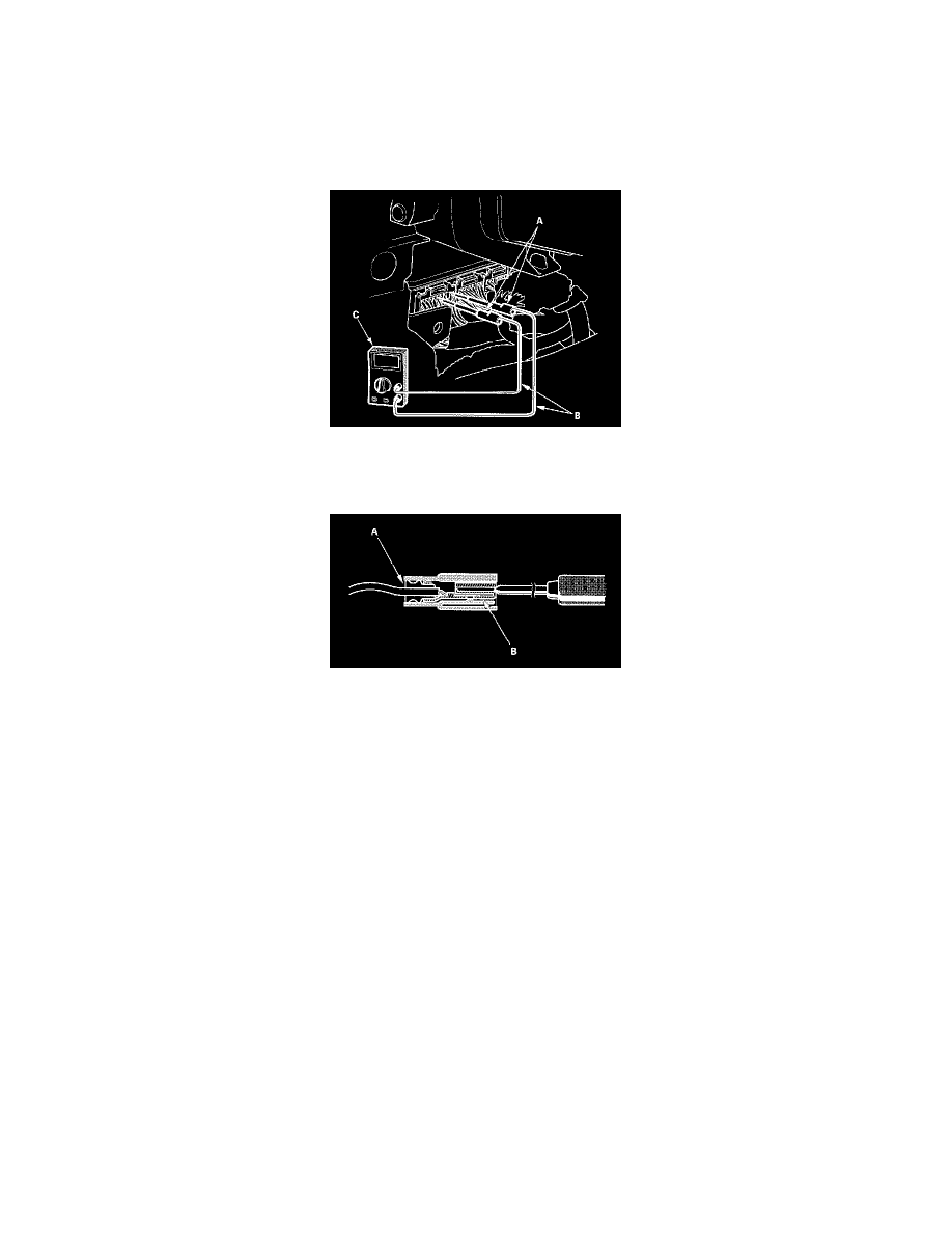
1. Connect the back probe adapters (A) to the stacking patch cords (B), and connect the cords to a digital multimeter (C).
2. Using the wire insulation as a guide for the contoured tip of the backprobe adapter, gently slide the tip into the connector from the wire side until it
touches the end of the wire terminal.
3. If you cannot get to the wire side of the connector or the wire side is sealed (A), disconnect the connector and probe the terminals (B) from the
terminal side. Do not force the probe into the connector.
NOTE: Do not puncture the insulation on a wire. Punctures can cause poor or intermittent electrical connections.