
RL V6-3.7L (2009)
Hydraulic Control Assembly - Antilock Brakes: Service and Repair
VSA Modulator-Control Unit Removal and Installation
NOTE:
-
Do not spill brake fluid on the vehicle; it may damage the paint; if brake fluid gets on the paint, wash it off immediately with water.
-
Be careful not to damage or deform the brake lines during removal and installation.
-
To prevent the brake fluid from flowing, plug and cover the hose ends and joints with a shop towel or equivalent material.
Removal
1. Make sure the ignition switch is LOCK (0).
2. Remove the right upper fender trim.
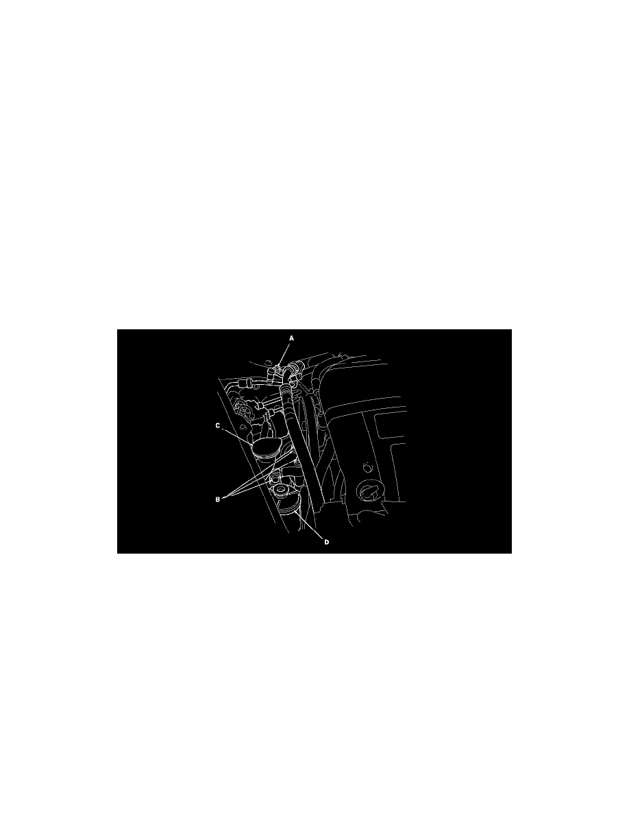
3. Remove the A/C line mounting bolt (A).
4. Remove the engine mount bracket mounting bolts (B).
5. Remove the upper portion of the washer reservoir (C).
6. Remove the power steering fluid reservoir (D) bracket.
7. Pull down the lock (A) of the VSA modulator-control unit 47P connector (B), and the connector disconnects itself.
8. Disconnect the six brake lines from the VSA modulator-control unit (C).
9. Disconnect the harness clip (D).
10. Remove the three 6 mm bolts, then remove the VSA modulator-control unit with bracket (E) from the body.
11. Remove the three 6 mm bolts, then remove the VSA modulator-control unit from the bracket.